
Top 10 Adapter & Adaptation Kits Manufacturers for Water and Wastewater
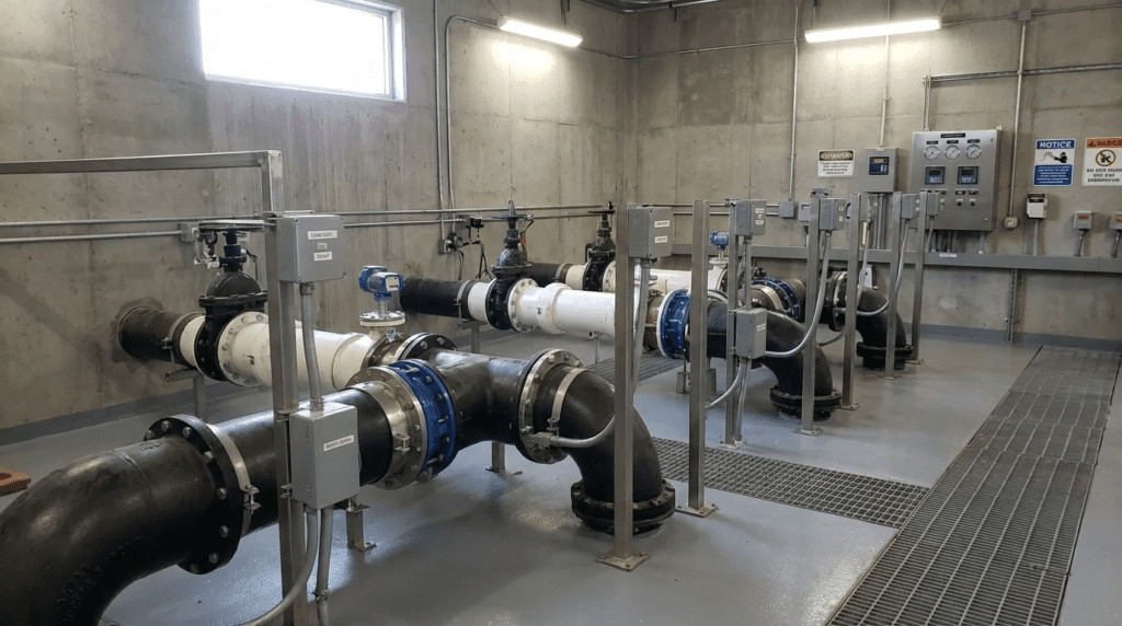
Introduction
One of the most persistent challenges in water and wastewater engineering is the interface between disparate systems. Whether connecting a new ductile iron pipeline to an existing asbestos-cement main, retrofitting a modern submersible pump onto a 30-year-old discharge elbow, or automating manual valves with electric actuators, the success of the project often hinges on the connection point. Engineers frequently underestimate the complexity of these interfaces, leading to field modifications that compromise system integrity. Utility asset management experience consistently shows that while pipe barrels may last 50 to 100 years, the joints, adapters, and connection points account for a disproportionate share of leakage and premature failures.
This article provides a rigorous technical analysis for specifying and selecting the Top 10 Adapter & Adaptation Kits Manufacturers for Water and Wastewater. In this context, “adapters and adaptation kits” refers to a broad category of critical interface equipment: flange coupling adapters (FCAs), universal pipe couplings, pump base retrofit rail kits, and valve actuation mounting kits. These components serve as the “translators” between different standards (ANSI vs. DIN), different eras of installation (imperial vs. metric), and different equipment manufacturers.
Typical applications range from emergency repair clamps in distribution networks to complex lift station rehabilitation where dry-pit pumps are converted to submersible service. Adapters sit alongside the broader family of water treatment equipment in a plant’s asset register, but they are procured differently—often as a line item within a larger installation rather than as an evaluated asset in their own right, which is precisely why they receive less engineering scrutiny than their failure consequences justify. Proper specification is not merely about finding a part that fits physically; it involves analyzing thrust restraint, galvanic compatibility, deflection capability, and long-term elastomeric performance. Poor selection leads to catastrophic joint separation, vibration-induced fatigue, and excessive operations and maintenance (O&M) costs. This guide aims to equip municipal engineers and plant directors with the data needed to make defensible, lifecycle-focused decisions.
Adaptation Kit Categories and Specialist Suppliers
The adapter category spans two quite different engineering problems that happen to share a name. Pipe-side adaptation solves a dimensional and sealing problem between pipe materials, standards, and eras. Equipment-side adaptation solves a mechanical interface problem between a machine and its mounting, its drive, or its predecessor. The manufacturers who excel at one are frequently absent from the other, and the specification language, testing requirements, and failure modes differ substantially.
Valve-Actuator Adaptation Kit Manufacturers
Where pipe couplings are largely catalog products selected against a measured dimension, the field of valve-actuator adaptation kit OEMs operates on an engineered-to-order basis. Each kit bridges a specific valve’s top-works—stem diameter, keyway or flats geometry, thrust base arrangement, and bolt circle—to a specific actuator’s ISO 5211 mounting face and drive bushing. There is no universal part, and the accuracy of the field survey largely determines whether the kit works on the first attempt.
Three considerations separate a durable automation retrofit from a troublesome one. First, torque capacity must be verified against the valve’s actual breakaway requirement after years of service, not against the manufacturer’s original figure for a new valve; a seized or scaled valve can require several times its as-built torque. Second, the stem itself must be capable of transmitting that torque without yielding, which is a genuine constraint on older valves with corroded or undersized stems. Third, backlash in the coupling assembly directly degrades control performance, so a modulating application demands tighter tolerancing than an open-close application. Specifying conformance to ISO 5211 at the actuator interface preserves the ability to change actuator brands later without refabricating the bracket.
Where Pipe and Equipment Adaptation Diverge
The practical guidance for specifiers is to treat these as separate procurement exercises with separate submittal requirements. Pipe-side adapters are evaluated on measured outside diameter, pressure and restraint rating, coating system, and elastomer compatibility, and they are typically stocked or short-lead. Equipment-side kits are evaluated on dimensional survey accuracy, torque or load path capacity, and material compatibility with a submerged or corrosive environment, and they carry engineering lead time that must be built into the construction schedule. Projects that lump both into a single “adapters and fittings” specification section routinely under-specify the equipment-side kits and discover the omission during shop drawing review.
How to Select / Specify
When evaluating the Top 10 Adapter & Adaptation Kits Manufacturers for Water and Wastewater, engineers must move beyond the catalog datasheet and evaluate the equipment against the specific constraints of the hydraulic and physical environment. The following criteria define the engineering operating envelope.
Duty Conditions & Operating Envelope
The first step in specification is defining the hydraulic profile. Adapters are often the weak link in a pressure class hierarchy.
- Pressure Ratings: Verify the working pressure (WP) and the test pressure. A common error is specifying an adapter rated for 150 psi in a system with surge potentials of 250 psi. Ensure the manufacturer’s rating applies to the specific pipe material being connected; some restrainers have lower ratings on PVC than on Ductile Iron.
- Transient Pressures: Coupling adapters allow for some movement, but excessive water hammer can cause “pumping” of the gasket, leading to eventual seal failure.
- Vacuum Conditions: If the line is subject to siphonage or rapid draining, the adapter gasket must be designed to resist being sucked into the pipe annulus. Flush-fit or vacuum-rated gaskets may be required.
- Deflection: Determine the angular deflection required. Rigid flange adapters allow zero deflection, while wide-range couplings may allow 3 to 5 degrees per end. This is critical in areas with shifting soils.
Materials & Compatibility
Material science is paramount in wastewater environments where hydrogen sulfide (H2S) and industrial effluents are present.
- Corrosion Resistance: For wastewater, 316 Stainless Steel hardware is the baseline requirement. For bodies, fusion-bonded epoxy (FBE) coating meeting AWWA C213 is standard. However, check the coating thickness (typically 10-12 mils minimum).
- Galvanic Isolation: When connecting dissimilar metals (e.g., steel pipe to a ductile iron valve), the adapter serves as a potential galvanic cell. Dielectric sleeves or insulating boot kits may be necessary.
- Elastomers: Specification of the gasket material is critical.
- EPDM: Standard for water and many wastewaters; excellent ozone resistance.
- NBR (Buna-N): Required if hydrocarbons, oils, or grease are present in the wastewater.
- FKM (fluoroelastomer): Necessary for high-temperature industrial effluents or aggressive chemical dosing lines.
Hydraulics & Process Performance
Adapters can introduce minor head loss, but in pump suction applications, turbulence is the primary concern.
- Turbulence and NPSH: An ill-fitted adapter on a pump suction side can induce pre-rotation or turbulence, artificially increasing Required Net Positive Suction Head (NPSHr). Ensure the internal diameter (ID) of the adapter matches the pipe ID closely to prevent steps or ledges.
- Solids Handling: In raw sewage, internal ridges or gaps in coupling adapters can collect rags (ragging). Flush-bottom adapters or continuous-sleeve designs are preferred for sludge lines.
Installation Environment & Constructability
The “constructability” of an adapter often dictates the installed cost and reliability.
- Outer Diameter (OD) Variance: Old water systems are notorious for non-standard pipe sizes (e.g., Pit Cast Iron vs. Spun Cast). “Wide-range” adapters are valuable here, but engineers must verify the specific range covers the actual field-measured OD, not just the nominal size.
- Restraint Mechanisms: In tight vaults where concrete thrust blocks are impossible to pour, mechanical joint restraints or integrated restraint couplings are mandatory. The specification must explicitly state if the adapter must be self-restraining.
- Pump Retrofits: For pump base adaptation kits (converting one manufacturer’s pump to another’s rail system), the critical dimension is the “hook” geometry and the discharge flange centerline. 3D scanning is often used now to fabricate precise retrofit adapters without modifying concrete.
Reliability, Redundancy & Failure Modes
Understanding how an adapter fails allows for better risk mitigation.
- Bolt Relaxation: Over time, gasket compression can lead to bolt relaxation. Manufacturers that utilize hydraulic pressure-assist gaskets often provide higher long-term reliability as the seal improves with line pressure.
- Shear Failure: In unburied or suspended applications, the weight of the valve or pipe spool must not be supported by the adapter unless specifically rated for shear loads.
- Redundancy: For critical large-diameter mains, specify double-bolt or multi-bolt constraints rather than single-bolt clamp styles to ensure a single bolt failure does not result in total blowout.
Controls & Automation Interfaces
This applies primarily to valve adaptation kits (mounting actuators to manual valves).
- Stem Nut Compatibility: The adaptation kit must precisely match the valve stem nut to the actuator drive sleeve. Poor tolerancing here leads to backlash (hysteresis), causing the control loop to hunt.
- ISO Mounting: Specify conformance to ISO 5211 for actuator mounting flanges. This ensures future interchangeability of actuators without replacing the mounting bracket.
- Drive Coordination: Where the automation retrofit also introduces speed control on associated pumps or blowers, the actuator scope should be coordinated with the drive scope. Selection of variable frequency drive OEMs and the actuator supplier together avoids the common outcome of two control philosophies coexisting in one station with incompatible communication protocols.
Maintainability, Safety & Access
- Single-Bolt vs. Multi-Bolt: For maintenance crews, “stab-fit” couplings that slide on without disassembling bolts are safer and faster, reducing time in the trench.
- Coating Repair: Field welds or cuts on adapters damage epoxy coatings. Specifications should require field repair kits (epoxy sticks or liquid install) be supplied with the hardware.
Lifecycle Cost Drivers
- Inventory Reduction: Utilities can reduce OPEX by stocking “universal” or wide-range couplings that fit multiple pipe materials (AC, DI, PVC, Steel) within a nominal size, rather than stocking specific adapters for each.
- Energy Impact: While minimal for pipe adapters, pump adapters that restrict flow or cause turbulence increase pumping energy costs over the 20-year life of the station.
Selection & Specification Framework
The criteria above are individually straightforward. What produces field failures is applying them out of order—most commonly, selecting an adapter from a catalog against a nominal pipe size and discovering the actual outside diameter, the thrust condition, or the restraint requirement during installation, when the options have narrowed to whatever is on the truck.
Step 1: Measure Before Selecting
Establish the actual outside diameter, wall condition, ovality, and surface quality of every pipe end the adapter will engage. Nominal size is not a dimension. Where the pipe is buried and cannot be exposed before procurement, specify wide-range products and state the assumed range explicitly, so that a field discovery outside that range is a documented change rather than an improvised fix.
Step 2: Determine the Thrust Condition
Identify every location where unbalanced hydraulic force exists—bends, tees, reducers, dead ends, and valve locations—and decide for each whether the thrust will be carried by a concrete block, by restrained joints, or by a combination. This decision precedes product selection because it determines whether a friction coupling is even admissible. A flexible coupling installed where restraint was required will hold during hydrostatic test and separate later under a transient.
Step 3: Worked Thrust Force Example
Consider a 16-inch ductile iron main terminating in a dead end within a vault where no thrust block can be poured. The nominal 16-inch pipe has an outside diameter of roughly 17.4 inches, giving a cross-sectional area of approximately 238 square inches. At a test pressure of 200 psi, the unbalanced thrust at the dead end is pressure multiplied by area: 200 times 238, or roughly 47,600 pounds—close to 24 tons acting to push the pipe out of the fitting. A friction-type coupling contributes essentially nothing against that force. The restraint system must be rated for the full thrust with an appropriate safety factor, typically requiring a restrained flange adapter or a wedge-action restraint device with a published rating at or above the test pressure for that specific pipe material.
The same calculation on a 90-degree bend yields a resultant thrust of the straight-run value multiplied by roughly 1.41, or about 67,000 pounds at the same pressure and diameter, directed along the bisector of the bend. Running this arithmetic at design time—rather than trusting that a coupling rated for 200 psi working pressure is therefore adequate at a dead end—is the single most valuable discipline in this category. Pressure rating and restraint rating are different specifications, and a product can satisfy one while failing the other entirely.
Step 4: Match Materials to the Actual Environment
Select hardware grade, coating system, and elastomer against the buried or submerged environment rather than the conveyed fluid alone. A coupling on a potable main in a wet, H2S-laden vault sees a more aggressive external environment than internal. Specify 316 stainless hardware with anti-galling treatment for buried and damp service, and confirm coating thickness rather than accepting the word “epoxy.”
Step 5: Coordinate the Electrical and Control Scope
Where the adaptation work is part of a station automation or rehabilitation project, confirm that the electrical scope has been sized for the added loads and control points. Actuator retrofits add motor loads, control wiring, and I/O that the existing gear may not accommodate, which is why motor control center OEM selection and the adaptation kit scope should be developed together rather than sequentially. Discovering at installation that the MCC has no spare bucket is a schedule problem that no adapter design resolves.
Step 6: Build the Submittal Requirements Around Failure Modes
Require, at minimum: measured OD range with the product’s published range shown to bracket it in the middle third, pressure rating and restraint rating stated separately, coating type and thickness, hardware grade, elastomer compound with a chemical compatibility statement, maximum gap and deflection limits, and installation torque values. Each of these corresponds to a documented failure mode, and a submittal that omits one is a submittal that has not been reviewed against how these products actually fail.
Comparison Tables
The following tables provide a structured comparison of the leading manufacturers in the adapter and adaptation kit market. Table 1 focuses on the primary manufacturers (OEMs) and their areas of specialization. Table 2 provides a selection matrix based on application scenarios to assist engineers in matching the technology to the problem.
| Manufacturer / Brand | Primary Strengths / Focus | Key Product Series | Typical Applications | Limitations / Considerations |
|---|---|---|---|---|
| 1. Hymax (Krausz / Mueller) | Wide-range coupling technology; top-bolt installation; dynamic deflection capabilities. | Hymax 2, Versa | Repair of diverse pipe materials; ground settling areas; quick emergency response. | Premium pricing; strict torque requirements to prevent crushing smaller OD pipes. |
| 2. Smith-Blair | Extensive range of clamp and coupling products; custom fabrication speed. | Top Bolt (912), Quantaflex | Main breaks, tapping sleeves, joining plain-end pipe to flanges. | Standard epoxy coatings may need upgrading for aggressive wastewater; vast catalog requires precise part number selection. |
| 3. Romac Industries | Fabricated steel and ductile iron couplings; specialized couplings for large dimensional variances. | Macro, Alpha | Large diameter transmission mains; connecting rough-barrel AC pipe. | Large fabricated units can be heavy and require mechanical lifting assistance in trenches. |
| 4. Ford Meter Box | Uni-Flange adapters; restraint reliability; strong distribution network focus. | Uni-Flange Series 1400 | Pump station piping; restraining plain end pipe to valves/fittings without welding. | Set-screw restraint mechanism marks the pipe surface (normal, but requires coating repair if removed). |
| 5. EBAA Iron | Widely specified joint restraint technology; wedge-action mechanical joint restraints. | Megalug, Flex-Tend | Restraining mechanical joints; seismic expansion joints for fault lines and bridge crossings. | Primary focus is restraint rather than repair couplings; specialized installation procedure for wedges. |
| 6. Victaulic | Grooved and shouldered mechanical pipe joining systems; high speed of assembly. | AWWA Grooved Systems | Plant piping (WTP/WWTP); exposed gallery piping; easy maintenance access. | Requires pipe preparation (grooving or shouldering); generally not for buried repair of existing plain-end pipe. |
| 7. Viking Johnson (Crane) | Large diameter couplings; dedicated and wide-range products; strong global presence. | AquaFast, UltraGrip | Large transmission mains; high-pressure applications; restraint plus coupling in one. | Lead times can be longer for non-standard large diameter units in North America. |
| 8. Flygt (Xylem) | Pump Adaptation: Retrofit kits to install pumps on existing competitor rail systems. | Plug-and-Play Adapters | Lift station rehabilitation; converting dry pit to submersible; avoiding concrete work. | Proprietary to pump interface; requires accurate dimensions of existing rails. |
| 9. Rotork | Valve Adaptation: Kits for mounting actuators to manual valves. | Valve Adaptation Kits (VAK) | Plant automation retrofits; SCADA integration projects. | Engineering intensive; requires precise measurements of valve top-works (stem, keyway, bolt circle). |
| 10. JCM Industries | Custom emergency fabrication; unusual sizes and adapters. | Surv-A-Rad, Universal Clamp | Emergency blowouts on non-standard pipe; out-of-round pipe repairs. | Ideally suited for repair/emergency rather than new construction specifications. |
| Application Scenario | Primary Constraint | Recommended Technology Type | Critical Specification Requirement | Relative Cost |
|---|---|---|---|---|
| Emergency Main Break | Speed of install; unknown exact Pipe OD. | Wide-Range Coupling (Top-Bolt) | Range must cover Pit Cast, DI, and AC classes. | Medium |
| Pump Station Gallery (New) | Vibration; Ease of disassembly for pump removal. | Dismantling Joint or Grooved Coupling | Must provide longitudinal adjustment for valve removal. | High |
| Buried Thrust Restraint (No Block) | Cannot pour concrete; soil instability. | Restrained Flange Adapter (wedge action) | Restraint rating at least 1.5 times test pressure. | Medium-High |
| Pump Retrofit (Existing Wet Well) | Cannot drain well; cannot drill new concrete. | Sliding Pump Bracket Adapter | Material: 316SS; verification of guide rail diameter. | Low (compared to civil work) |
| Valve Automation Retrofit | Valve is old; no ISO mounting pad. | Custom Valve Adaptation Kit (Spool & Drive) | Survey of valve stem condition; torque safety factor. | Medium |
| Rotating Equipment Mount Retrofit | Existing bridge, davit, or deck cannot be modified. | Fabricated Transition Plate or Mounting Spool | Load path verification including dynamic and torque loads. | Medium |
Engineer & Operator Field Notes
The difference between a successful installation and a future leak often lies in the field procedures. The following notes are compiled from commissioning reports and forensic engineering analysis of failed connections.
Commissioning & Acceptance Testing
Acceptance of adapter installations should not be passive. The following checkpoints are critical during the Site Acceptance Test (SAT):
- Hydrostatic Testing: Observe the adapter under test pressure. “Weeping” at the gasket face is often a sign of uneven torquing or debris on the pipe surface. Do not simply tighten bolts further; depressurize and inspect.
- Deflection Check: Verify that the adapter is not maxed out on its deflection limit during installation. If installed at maximum deflection, any ground settling will cause failure. The joint should ideally be installed in a neutral position.
- Restraint Engagement: For wedge-style restrainers, visually confirm that the break-off heads are snapped (if applicable) or that torque indicators show proper engagement.
Common Specification Mistakes
- “Or Equal” Ambiguity: Specifying a named product “or equal” without defining what constitutes equal regarding coating thickness, bolt material, or pressure rating often results in contractors supplying lighter-duty clamps that fail prematurely.
- Ignoring Pipe Ovality: Large diameter pipe (especially flexible pipes like HDPE or thin-wall steel) can be oval. Standard rigid flange adapters may not seal. Specifications must call for “tolerance for ovality” or require re-rounding rings.
- Under-specifying Hardware: Standard “shop bolts” corrode in months in wastewater atmospheres. Specification documents must explicitly require 304SS or 316SS bolts and nuts, preferably with anti-galling coating.
- Confusing Pressure Rating with Restraint Rating: A coupling rated for 250 psi working pressure is not thereby restrained for the thrust that 250 psi generates at a dead end. These are separate specifications and must both appear in the submittal.
O&M Burden & Strategy
- Torque Verification: While modern wide-range couplings are designed to hold torque, vibration can loosen them. A 1-year warranty inspection should include checking bolt torque on all accessible adapters.
- Spare Parts Inventory: It is impractical to stock every size. The strategy should be to stock wide-range couplings that cover critical pipe sizes (for example, a single coupling covering 6.60 to 7.20 inches OD).
- Maintenance of Actuator Adapters: Valve adaptation kits introduce a new maintenance point: the coupler. Grease the drive bushing annually to prevent seizing, which can cause the actuator to trip on high torque.
Troubleshooting Guide
- Symptom: Adapter slides off pipe under pressure.
Root Cause: Lack of restraint. A friction coupling is not a restraint. If there is no thrust block, the pipe will separate.
Fix: Install external tie-rods or replace with a restrained coupling. - Symptom: Gasket extrudes or blows out.
Root Cause: Gap between pipe ends is too large for the coupling length.
Fix: Use a longer-barrel coupling or verify the maximum gap specification on the datasheet. - Symptom: Actuator trips on torque partway through travel.
Root Cause: Seized drive bushing, misaligned coupling introducing side load, or a valve requiring more torque than surveyed.
Fix: Verify alignment and lubrication before increasing the torque limit setting; raising the limit on a binding assembly transfers the failure to the valve stem.
Retrofitting Rotating Equipment Mounts
Adaptation work extends beyond pipe and valve interfaces to the mounting of rotating equipment on existing structures. Mixers, aerators, and similar assets are frequently replaced on bridges, davits, or deck plates that were designed for a different machine, and the transition plate or mounting spool becomes a structural element carrying both static weight and dynamic torque reaction. The evaluation criteria differ from pipe adapters entirely: load path continuity, fatigue under cyclic loading, and natural frequency separation from the operating speed matter more than sealing or pressure rating. Where the retrofit involves comparing candidate machines, the differences between mixer equipment manufacturers in shaft length, overhung load, and mounting pattern often determine whether the existing support can be reused at all—a question worth answering before the machine is selected rather than after.
Design Details / Calculations
Engineering the interface requires understanding the forces at play. Here is the logic for sizing and specifying these components correctly.
Sizing Logic & Methodology
The most critical parameter is the Actual Outside Diameter (OD). Nominal sizes are misleading.
- Identify Pipe Material & Class: A 6-inch pipe could be:
- Steel (IPS): 6.625 inches OD
- Ductile Iron (DI): 6.90 inches OD
- Class 150 Asbestos Cement: 7.05 inches OD
- Rough Barrel AC: 7.20 inches OD
- Calculate Circumference: If calipers will not fit, measure the circumference (C) and divide by pi: OD = C ÷ 3.14159.
- Select Range: Choose an adapter where the measured OD falls within the middle third of the adapter’s published range. Avoid being at the absolute minimum or maximum.
- Verify Restraint Separately: Calculate the unbalanced thrust at the location (pressure multiplied by the pipe outside cross-sectional area, with a multiplier for bends) and confirm the restraint rating covers it with a safety factor, independent of the pressure rating.
Specification Checklist
When writing the specification for adapters and adaptation kits, ensure these lines are included:
- Compliance: Couplings shall meet or exceed AWWA C219.
- Coating: All ductile iron bodies shall be coated with fusion-bonded epoxy in accordance with AWWA C213, with minimum thickness stated.
- Bolting: Bolts and nuts shall be Type 316 Stainless Steel with anti-galling coating.
- Ratings: Working pressure, test pressure, and restraint rating shall each be stated separately for the specific pipe material.
- Range: Published OD range shall bracket the field-measured OD within the middle third.
- Gap and Deflection: Maximum permissible end gap and angular deflection per end shall be stated.
- Elastomer: Gasket compound identified with a chemical compatibility statement for the conveyed fluid and the external environment.
- Traceability: Manufacturer shall provide stamped range and pressure rating on the casting.
- Installation: Torque values and sequence shall be supplied, with a field coating repair kit included.
- Origin: (If applicable) Domestic manufacture required, or American Iron and Steel compliant.
Standards & Compliance
Engineers should reference the governing standards explicitly rather than by general description. AWWA C219 covers bolted, sleeve-type couplings for plain-end pipe and is the primary standard for this equipment class. AWWA C110 and AWWA C111 define ductile-iron and gray-iron fitting dimensions and mechanical joint rubber-gasket details respectively. AWWA C213 governs fusion-bonded epoxy coatings for interior and exterior steel surfaces, and AWWA C207 covers steel pipe flanges. Castings are verified to ASTM A536 for ductile iron. All wetted components in potable service must be certified to NSF/ANSI/CAN 61, with lead content governed by NSF/ANSI/CAN 372. For valve automation work, actuator mounting interfaces follow ISO 5211, and electric actuators for waterworks service are commonly specified to AWWA C542.
Certification marks should be verified against the certifying body’s public listing for the specific model and material configuration furnished, not accepted from a submittal cover sheet naming the manufacturer generally.
Frequently Asked Questions
What is the difference between a Flange Adapter and a Coupling?
A Flange Adapter connects a plain-end pipe to a flanged component (like a valve, pump, or meter). It has a flange on one side and a compression mechanism on the other. A Coupling connects two plain-end pipes together. It typically consists of a center sleeve and two compression glands.
When should I use a restrained adapter versus a standard adapter?
Restrained adapters are required whenever there is an unbalanced hydraulic force (thrust) and no external concrete thrust block is used. This occurs at bends, tees, dead ends, and reducers. If the pipe is simply buried in a straight line, a standard flexible coupling may suffice, but restrained adapters provide a higher factor of safety against ground movement. The Design Details section above sets out the thrust calculation and the governing standards.
Can I use adaptation kits to mount any actuator to any valve?
Generally, yes, but it requires custom engineering. Adaptation kits (brackets and couplers) bridge the gap between the valve’s top-works mounting pattern and the actuator’s ISO base. However, if the valve stem is bent or the valve requires more torque than the stem can handle, the adaptation kit will not solve the underlying mechanical issue.
How do I retrofit a submersible pump without draining the wet well?
Several manufacturers offer universal adapter rails. These devices bolt onto the new pump’s discharge flange and include a hook profile designed to mate with the existing guide rail system and discharge elbow in the wet well. This eliminates the need to enter the well to unbolt the old base elbow, saving significant bypass pumping costs.
What is the typical lifespan of a coupling adapter gasket?
In standard water and wastewater service, high-quality EPDM or NBR gaskets can last 20 to 40 years if protected from direct UV exposure and extreme heat. Failure usually occurs due to bolt corrosion or pipe movement rather than gasket degradation. However, in aggressive industrial wastewater, gasket life may be reduced to 5 to 10 years depending on chemical compatibility.
Why do some engineers specify “dismantling joints” instead of flange adapters?
A dismantling joint is essentially a double-flanged composite fitting that acts as a flange adapter but includes tie-rods for restraint. Its primary advantage is longitudinal adjustability; it can be collapsed to create a gap, allowing maintenance crews to remove a valve or pump without straining the piping system. They are standard best practice in pump station design.
How is thrust force calculated at a dead end or bend?
At a dead end, thrust equals the internal pressure multiplied by the outside cross-sectional area of the pipe. A 16-inch ductile iron main at 200 psi generates roughly 47,600 pounds of unbalanced force. At a 90-degree bend, the resultant is approximately 1.41 times that value, directed along the bisector of the bend; shallower bends produce proportionally less. The point of running the calculation is that the resulting number is usually far larger than engineers expect, and it makes the distinction between a pressure-rated coupling and a restrained joint immediately concrete.
Why does a joint that passed hydrostatic testing fail months later?
Three mechanisms account for most delayed failures. Creep in flexible pipe materials, particularly HDPE, allows the pipe to deform inward under sustained clamp load, relaxing the seal after the test is long finished. Bolt relaxation as the gasket takes a compression set reduces the sealing force over months. And ground movement or thermal cycling loads a joint that was installed at or near its deflection limit, leaving no reserve. A successful hydrostatic test demonstrates that the joint sealed on the day; it says comparatively little about how the joint behaves under sustained and cyclic conditions.
Conclusion
Key Takeaways
- Verify OD, Not Nominal Size: The leading cause of field failure is assuming “6-inch pipe” is a universal dimension. Measure the actual OD and select so it falls in the middle third of the published range.
- Restraint is Mandatory: Friction couplings are not restraints. If you do not block it, you must restrain it—and pressure rating and restraint rating are separate specifications.
- Run the Thrust Arithmetic: A 16-inch dead end at 200 psi generates close to 24 tons of unbalanced force; the number is almost always larger than intuition suggests.
- Material Match: Use EPDM for water and sewage, NBR for hydrocarbons. Use 316SS hardware for all buried or damp service, selected against the external environment as well as the conveyed fluid.
- Wide-Range vs. Dedicated: Use wide-range adapters for repairs on unknown pipes; use dedicated tolerance adapters for new construction to save cost.
- Equipment-Side Kits Are Engineered, Not Stocked: Valve-actuator and pump retrofit kits carry survey requirements and engineering lead time that pipe couplings do not, and they belong in a separate specification section.
- Pump Retrofits: Use sliding adapter brackets to avoid civil work in wet wells, and dry-fit before committing.
Selecting from the Top 10 Adapter & Adaptation Kits Manufacturers for Water and Wastewater requires a balanced approach between upfront CAPEX and long-term OPEX. While it may be tempting to select the lowest-cost commodity coupling, the cost of a single excavation to repair a failed seal dwarfs the price difference between a generic product and a high-specification one.
For municipal engineers and operators, the goal is “bury and forget.” This is achieved by specifying the correct materials (stainless steel hardware, proper elastomer selection), ensuring the mechanical restraints match the hydraulic thrust forces, and utilizing the correct adaptation technology for the specific era and type of infrastructure being connected. Whether retrofitting a 1950s lift station or connecting a new PVC C900 main, the manufacturers listed in this guide provide the engineered solutions necessary to ensure system integrity. When in doubt, involve the manufacturer’s application engineer early in the design phase to verify chemical compatibility and dimensional fit.