UV Systems for Wastewater Treatment: Types and Applications
Introduction: The Shift to Ultraviolet Disinfection
One of the most persistent challenges municipal and industrial wastewater engineers face is balancing stringent disinfection requirements with the environmental and safety risks associated with chemical treatment. For decades, chlorine contact basins were the default standard. However, the regulatory tightening around disinfection byproducts (DBPs), the stringent limits on total residual chlorine (TRC) in effluent discharges, and the inherent occupational hazards of handling gaseous chlorine or sodium hypochlorite have forced a massive industry shift. Today, understanding UV Systems for Wastewater Treatment: Types and Applications is an absolute necessity for modern plant design and operation.
Ultraviolet (UV) disinfection is a physical, chemical-free process that relies on specific wavelengths of light to inactivate pathogenic microorganisms. Unlike chlorination, UV does not alter the physical or chemical properties of the water, nor does it create harmful residuals. It is deployed globally across municipal wastewater plants, advanced water reuse facilities, and industrial effluent treatment systems. Operating environments range from secondary clarifier effluent in standard municipal plants to high-transmittance reverse osmosis (RO) permeate in direct potable reuse (DPR) trains.
Despite its widespread adoption, UV technology is frequently misunderstood. Missteps in calculating UV Transmittance (UVT), ignoring peak hourly flow hydraulics, or misunderstanding the lifecycle costs of lamp replacements and quartz sleeve fouling can cripple a plant’s operations. Poorly specified systems lead to failed compliance tests, excessive energy consumption, and unsustainable maintenance burdens. This comprehensive guide provides consulting engineers, utility decision-makers, and plant operators with the technical foundation required to select, design, and maintain UV disinfection systems based on real-world performance, reliability, and lifecycle cost analysis.
Core Technical Content: System Fundamentals and Design
How It Works / Process Fundamentals
Ultraviolet disinfection relies on the emission of electromagnetic radiation in the germicidal UVC spectrum, primarily between 200 and 300 nanometers (nm), with the peak germicidal effectiveness occurring at approximately 254 nm. When wastewater passes through the UV reactor, the UVC energy penetrates the cell walls of bacteria, viruses, and protozoa (such as Cryptosporidium and Giardia).
The photons are absorbed by the microorganisms’ nucleic acids (DNA and RNA). This absorption causes the formation of pyrimidine dimers (specifically thymine dimers in DNA and uracil dimers in RNA), which physically distorts the DNA helix. This structural damage prevents the microorganism from replicating. Because a pathogen that cannot replicate cannot cause infection, it is considered microbiologically inactive or “dead” for regulatory purposes.
The core principle governing this process is the UV Dose, which is the product of UV intensity and exposure time. The fundamental equation is:
Dose (mJ/cm²) = Intensity (mW/cm²) × Time (seconds)
However, in highly turbulent, real-world wastewater environments, velocity profiles are non-uniform, and UV intensity decreases exponentially as it travels through the water. Therefore, engineers must rely on the Reduction Equivalent Dose (RED), which is determined through biological validation testing rather than simple mathematical calculation.
Types, Configurations & Technologies
When evaluating UV Systems for Wastewater Treatment: Types and Applications, engineers must first select the appropriate lamp technology and physical configuration. The market is dominated by three primary lamp technologies:
- Low-Pressure, Standard Output (LPSO): Emits monochromatic light at 254 nm. Due to low wattage (typically 40-100W per lamp), an excessive number of lamps is required for municipal wastewater flow rates. LPSO is largely obsolete in modern municipal design, relegated to small commercial or residential systems.
- Low-Pressure, High-Output (LPHO) & Amalgam: The industry standard for wastewater. Amalgam lamps use a solid amalgam of mercury and other metals, allowing them to operate at higher internal temperatures and power levels (typically 250W to 1000W+ per lamp). They emit monochromatic light at 254 nm and offer the best electrical efficiency (approx. 30-40% conversion of electricity to UVC) and longest operating life (typically 12,000 to 15,000 hours).
- Medium-Pressure (MP): Operates at much higher temperatures and pressures, emitting a polychromatic spectrum across a wide UVC range. MP lamps draw immense power (often 3kW to 20kW+ per lamp) and offer extremely high intensity, meaning very few lamps are required. Consequently, the footprint is extremely compact. However, MP lamps suffer from lower UVC conversion efficiency (approx. 10-15%) and shorter lifespans (typically 4,000 to 8,000 hours).
- UV-LED (Emerging): Solid-state UV light-emitting diodes offer instant on/off capabilities, zero mercury content, and targeted wavelength emissions (e.g., 255 nm, 265 nm, 275 nm). While promising, UV-LED technology is currently limited in individual diode output, making it capital-prohibitive for large-scale municipal wastewater applications. It is currently gaining traction in low-flow, point-of-use industrial and advanced reuse applications.
System configurations generally fall into two categories:
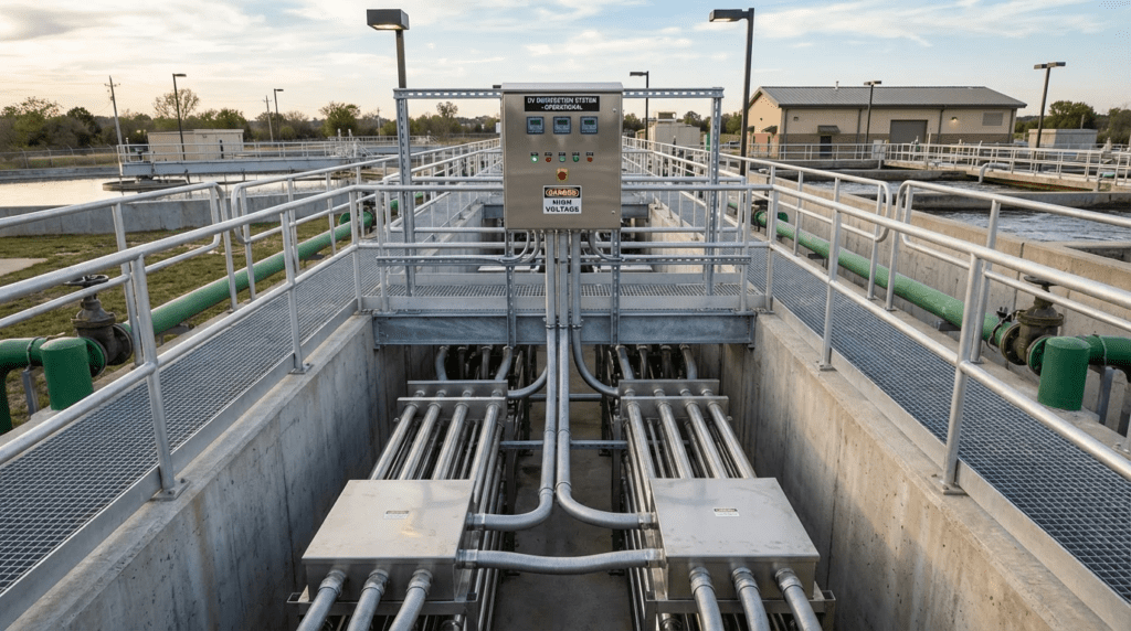
- Open-Channel Systems: The standard for municipal wastewater. UV modules (banks of lamps) are submerged directly into a concrete channel. Flow is driven by gravity. Lamps can be arranged horizontally (parallel to the flow) or vertically (perpendicular to the flow). Open-channel systems require careful hydraulic design to control water levels via an automatic level-control gate or a fixed weir.
- Closed-Vessel Systems: Lamps are housed inside a pressurized stainless-steel pipe reactor, typically installed inline with existing piping. Commonly used in advanced water reuse (e.g., RO permeate), industrial effluents, or where hydraulic head cannot be sacrificed for an open channel.
Operating Conditions & Duty Requirements
The successful application of a UV system dictates that the equipment must operate under a specific set of boundary conditions. UV is highly sensitive to changes in wastewater quality. The most critical operating conditions include:
- Peak Hourly Flow (PHF): UV systems must be sized to deliver the required validation dose at the absolute highest flow rate, typically during wet weather events. Because UV has no residual, undertreating a peak flow surge instantly results in non-compliant effluent.
- UV Transmittance (UVT): Measured at 254 nm using a 1 cm path length cell, UVT is the percentage of UV light that can pass through the water. Pure water is ~100% UVT. Standard secondary municipal wastewater is typically 60-65% UVT. Advanced reuse water is 90-95% UVT. A drop in UVT exponentially decreases the intensity of light reaching pathogens. Designing for an overly optimistic UVT is the single most common cause of UV system failure.
- Total Suspended Solids (TSS): High TSS values shield pathogens from UV light. If a bacterium is embedded within a solid particle, the UV light cannot penetrate the particle to inactivate it. Municipal UV systems typically require TSS to be consistently below 30 mg/L, with advanced systems requiring less than 5 mg/L to achieve high-level (e.g., Title 22) disinfection.
Hydraulic & Process Performance
Hydraulics dictate dose delivery. If water short-circuits through a reactor, some pathogens receive an extremely high dose, while others receive a sub-lethal dose, leading to failed compliance. In open channels, strict approach velocity limits (typically 0.5 to 1.5 ft/sec) must be maintained. If velocity is too low, solids settle in the channel, creating a breeding ground for bacteria. If velocity is too high, headloss becomes excessive, and contact time drops below the required minimum.
Furthermore, the water level must be rigorously maintained. If the water level drops too low, the uppermost lamps are exposed to air, causing them to overheat and fail prematurely. If the water level rises too high, water passes over the top of the lamp modules untreated. Submerged fixed weirs or motorized level-control gates (often counterweighted flap gates or overshot gates) are utilized to maintain a tight tolerance (usually +/- 1 inch) regardless of flow.
Materials & Compatibility
Wastewater is highly corrosive. Open-channel structural frames, module chassis, and closed-vessel reactor bodies must be constructed of 316L Stainless Steel to resist corrosion from chlorides, hydrogen sulfide, and acidic cleaning chemicals. Passivation and electropolishing are often specified to smooth the steel surface, preventing biofilm attachment and minimizing corrosion sites.
The UV lamps are isolated from the water by Quartz Sleeves. Type 214 fused quartz is typically used because it allows greater than 90% transmission of UVC light (standard glass blocks UVC). Elastomeric seals (O-rings) used to seal the quartz sleeves must be highly resistant to both UVC degradation and chemical attack; FKM (Viton) or specially formulated EPDM are standard.
Controls, Automation & SCADA Integration
Modern UV systems rely on sophisticated Power Distribution Centers (PDCs) and System Control Centers (SCCs). Unlike older systems that ran at 100% power continuously, modern LPHO/Amalgam systems utilize variable-output electronic ballasts. Through SCADA integration (typically via Modbus TCP/IP, Ethernet/IP, or Profinet), the system employs two primary control strategies:
- Flow Pacing: The plant SCADA provides a real-time flow signal to the UV controller. The controller turns specific lamp banks on or off, or dims the ballasts, to match the minimum required dose for that specific flow rate.
- Dose Pacing: A more advanced strategy. The system calculates real-time dose utilizing inputs from the plant flow meter, online UVT monitors, and submerged UV intensity sensors. The PLC mathematically computes the real-time RED and automatically dims ballasts (typically down to 30-50% power) to maintain the exact dose required by the permit. This minimizes electrical consumption and extends lamp life.
Maintainability, Safety & Operator Access
Operator intervention is the largest OPEX driver aside from energy. The foremost maintenance task is combating quartz sleeve fouling. As heat from the lamps interacts with wastewater, minerals (especially calcium, magnesium, and iron) and organics precipitate onto the quartz sleeves, blocking UV light.
To combat this, automatic wiping systems are specified. Mechanical Wipers use Teflon rings or brushes driven by pneumatic or electric actuators to physically scrape the sleeves. Chemical-Mechanical Wipers incorporate a hollow wiper collar filled with a mild acid (typically citric or phosphoric acid); as the wiper moves, it bathes the sleeve in acid, dissolving mineral scales that physical wiping cannot remove.
Safety is critical. UV ballasts operate at lethal voltages. Systems must be designed with robust lockout/tagout (LOTO) points and automatic power-kill switches if a module is lifted out of the channel. Furthermore, operators must be protected from UVC exposure, which causes severe arc eye (photokeratitis) and skin burns. Systems utilize grating and stainless steel covers to ensure zero UVC light escapes the channel.
Comparison Tables for UV Systems
The following tables provide an unbiased comparison of technology types and application fits. Use Table 1 to select the underlying lamp technology based on footprint and lifecycle costs. Use Table 2 to determine the correct physical configuration based on your specific wastewater matrix and plant constraints.
Table 1: UV Lamp Technology Comparison
| Technology Type | Key Characteristics | Primary Strengths | Limitations / Considerations | Typical Maintenance Profile |
|---|---|---|---|---|
| Low-Pressure High-Output (LPHO) / Amalgam | Monochromatic (254 nm); 250W–1000W per lamp; ~40% electrical efficiency. | Excellent lifecycle cost; longest lamp life; high energy efficiency; stable temperature profile. | Requires a larger footprint and more lamps than MP systems; larger channel construction. | Lamp replacement every 12,000–15,000 hrs. Routine wiper seal replacements. |
| Medium-Pressure (MP) | Polychromatic (broad UVC); 3kW–20kW+ per lamp; ~15% electrical efficiency. | Extremely compact footprint; treats massive flows with very few lamps; highly effective against certain robust viruses. | High energy consumption; high heat generation (can cause rapid sleeve scaling); shorter lamp life. | Lamp replacement every 4,000–8,000 hrs. Requires frequent, aggressive sleeve cleaning. |
| UV-LED (Solid State) | Targeted wavelengths (e.g., 265 nm); Instant on/off; Low power per diode. | Zero mercury; extremely robust physical design; no warm-up time; flexible reactor geometry. | High capital cost per mW of output; currently unfeasible for large municipal flows. | Minimal routine maintenance; eventual full board/module replacement at end of life. |
Table 2: UV Configuration Application Matrix
| Application Scenario | Open Channel (Horizontal) | Open Channel (Vertical/Inclined) | Closed Vessel (Pressurized) |
|---|---|---|---|
| Standard Municipal WWTP (Gravity Flow) | Best Fit: Standard industry practice. Excellent hydraulic profile, easy module lifting. | Good Fit: Requires a deeper, narrower channel. Good for highly constrained footprints. | Poor Fit: Induces unnecessary headloss. Pumping is often required. |
| Advanced Water Reuse / Title 22 (Low TSS) | Good Fit: Works well if channels are heavily covered to prevent algae growth. | Good Fit: Effective for deep channels processing tertiary effluent. | Best Fit: Complete isolation from airborne contaminants; handles high-pressure upstream processes. |
| CSO / SSO High-Flow Bypass Treatment | Good Fit: Can handle massive gravity flows if properly baffled. | Best Fit: Vertical systems with alternating banks handle extreme variable flows efficiently. | Poor Fit: Pipe diameters required for CSO peak flows are prohibitively massive and expensive. |
| Industrial Wastewater (High Temp, Corrosive) | Poor Fit: Odor and off-gassing issues in open channels; hazard to operators. | Poor Fit: Same atmospheric exposure risks as horizontal open channels. | Best Fit: Completely contained. Can be manufactured from high-nickel alloys (e.g., Hastelloy) if required. |
Engineer & Operator Field Notes
Commissioning & Acceptance Testing
Commissioning UV systems goes far beyond flipping a switch. Site Acceptance Testing (SAT) must meticulously verify hydraulic performance and sensor integration. A critical checkpoint is the dye tracer test or velocity profiling. Engineers should require testing across the entire channel cross-section to verify that velocities remain within 10-15% of the average velocity. Flow short-circuiting at the channel invert or along the walls will guarantee failed fecal coliform or E. coli tests down the line.
Additionally, UV intensity sensors must be calibrated against a primary reference standard during SAT. Ensure the SCADA system correctly scales the 4-20mA signals from the UV control panel and that dose-pacing algorithms successfully ramp ballasts up and down in response to manual flow overrides.
Common Specification Mistakes
When specifying UV Systems for Wastewater Treatment: Types and Applications, engineers routinely make errors that cost utilities millions over the system’s lifecycle:
- Optimistic UVT Assumptions: Specifying an average UVT of 65% instead of a 5th-percentile worst-case UVT of 55%. This drastically undersizes the system, leading to non-compliance during process upsets.
- Ignoring Headloss Limitations: Failing to account for the hydraulic restriction caused by the UV modules, support racks, and downstream level-control gates. This can back up water into upstream clarifiers, causing weir submergence.
- Sole-Sourcing via Geometry: Designing channel dimensions that strictly fit only one manufacturer’s module size. This eliminates competitive bidding. Engineers should design a “generic” channel envelope and require the selected manufacturer to provide flow-baffling to adapt to the civil structure.
O&M Burden & Strategy
A successful maintenance strategy acknowledges the realities of biological and chemical fouling. Plant operators must balance the replacement of critical wear parts. While manufacturers boast 12,000-hour lamp lives, operators must track the actual power consumption. As lamps age, dose-pacing systems must drive more power to them to maintain intensity. Eventually, it is more economically viable to replace the lamp than to pay the energy premium of running aged lamps at 100% power.
For chemical cleaning, operators must manage acid inventory. Plants utilizing automatic chemical-mechanical wipers must routinely refill the wiper fluid reservoirs (often a proprietary citric acid blend). Routine inspections should verify that the pneumatic air lines driving the wipers are free of moisture, as wet instrument air will destroy the pneumatic cylinders on the UV frames.
Troubleshooting Guide: The Low Dose Alarm
The most common headache for an operator is a persistent “Low Dose” alarm. When diagnosing this, follow a systematic approach:
- Verify the Flow: Is the plant experiencing a massive hydraulic surge beyond the system’s design capacity? If yes, additional banks must be brought online.
- Check the UVT Monitor: Has the upstream process failed? A spike in TSS from a clarifier washout will plummet the UVT. The UV system is not broken; it is accurately reporting that the water is un-treatable.
- Inspect the Quartz Sleeves: Are they coated in a white, chalky scale or a brown iron film? If so, the wiper system has failed or the acid reservoir is empty. The lamps may be firing perfectly, but the light is blocked.
- Examine the Sensors: UV intensity sensors foul just like sleeves. Pull the reference sensor, clean its optical window with isopropyl alcohol or mild acid, and reinstall. If the dose jumps back to normal, the sensor was simply blinded by fouling.
Design Details & Calculations
Sizing Logic & Methodology
The design of a wastewater UV system relies on the biological validation data provided by the manufacturer. Manufacturers run physical scale tests by injecting a surrogate organism (typically MS2 bacteriophage or T1 coliphage) into a reactor at varying flows and UVTs. This establishes the Validated Dose.
When an engineer sizes a system, they must account for real-world degradation over time. The mathematical relationship is:
Design RED = Validated Dose × LFA × FF
Where:
- LFA (Lamp Fouling/Aging Factor): Also known as End of Lamp Life (EOLL). Typically assigned a value of 0.50 to 0.80. This accounts for the degradation of UV output as the lamp’s filaments and gases age.
- FF (Fouling Factor): Typically 0.80 to 0.95. This accounts for the loss of transmission through the quartz sleeve due to mineral scaling between wiper cycles.
If a permit requires a minimum delivered RED of 30 mJ/cm², and the engineer applies an EOLL of 0.80 and an FF of 0.80, the system must be physically sized to deliver 46.8 mJ/cm² when lamps and sleeves are brand new and perfectly clean (30 / [0.8 × 0.8]). This safety margin ensures compliance on the day before the lamps are scheduled for replacement.
Specification Checklist
To ensure a robust procurement package, design engineers must include the following minimum requirements in their equipment specifications:
- Performance Guarantees: Explicitly state the Peak Hourly Flow (PHF), Minimum UVT (%), Maximum TSS (mg/L), and Target Pathogen Log Reduction or limit (e.g., <126 MPN/100mL E. coli).
- Validation Certification: Require third-party validation documentation (e.g., NWRI or USEPA UVDGM) specific to the proposed lamp, ballast, and reactor geometry. Extrapolating data from different configurations is unacceptable.
- Headloss Limits: Specify the maximum allowable hydraulic headloss at PHF (typically 2 to 6 inches, depending on channel design).
- Power Quality: Demand integrated harmonic filters. Large UV ballast arrays generate significant Total Harmonic Distortion (THD), which can damage upstream plant transformers and VFDs if unmitigated.
Standards & Compliance
Depending on the region and application, specific guidelines govern UV system design:
- NWRI/AWWARF Guidelines: The National Water Research Institute provides the de facto standard for wastewater and water reuse in the United States. It dictates strict redundancy requirements (e.g., “N+1 bank redundancy”) and rigorous bioassay validation protocols.
- USEPA UVDGM: The Ultraviolet Disinfection Guidance Manual is primarily for drinking water, but its protocols for sensor uncertainty, RED bias, and dose calculation are heavily utilized in advanced wastewater reuse.
- Title 22 (California Code of Regulations): For unrestricted water reuse, systems must achieve a minimum delivered dose (often 80 to 100+ mJ/cm²) and highly specific MS2 log-reduction targets. Equipment must be explicitly approved by the State Water Resources Control Board.
Frequently Asked Questions
What is the difference between open-channel and closed-vessel UV systems?
Open-channel systems place UV lamp modules directly into gravity-fed concrete channels, utilizing level-control gates to manage hydraulics. They are the standard for secondary municipal wastewater due to ease of maintenance and lack of pressure drop. Closed-vessel systems enclose the lamps in a pressurized stainless-steel pipe, installed inline. They are preferred for advanced reuse, high-pressure industrial flows, or plants with severe space/hydraulic head constraints.
How is the dose calculated for UV Systems for Wastewater Treatment: Types and Applications?
Dose is technically the product of UV intensity and exposure time ($D = I times t$). However, because wastewater flows are turbulent and UV intensity drops off exponentially in water, engineers use a Reduction Equivalent Dose (RED). RED is determined empirically through bioassay testing (injecting surrogate viruses) and adjusted downward in real-world design using safety factors for End of Lamp Life (EOLL) and Quartz Fouling Factor (FF).
What is UV Transmittance (UVT) and why is it critical?
UVT is a measure of the fraction of UV light (at 254 nm) that can pass through 1 cm of a water sample. It indicates how “transparent” the wastewater is to germicidal light. It is critical because a small drop in UVT (e.g., from 65% to 55%) exponentially reduces the effective dose delivered to pathogens. Systems designed for an incorrectly high UVT will fail to disinfect properly during process upsets.
How often should UV lamps and quartz sleeves be replaced?
For modern Low-Pressure High-Output (LPHO) and amalgam systems, lamps typically last between 12,000 and 15,000 operating hours (roughly 1.5 to 2 years) before degrading past their guaranteed output. Quartz sleeves generally last 5 to 8 years; they do not “burn out” but are replaced when they become permanently scratched, etched by chemicals, or irreversibly scaled, preventing light transmission.
Can UV systems treat high-TSS wastewater?
High Total Suspended Solids (TSS) severely impairs UV disinfection. Solid particles shield pathogens from the UV light—if a bacterium is inside a particle, the light cannot reach it. While UV can operate at 20-30 mg/L TSS in standard secondary municipal effluents, advanced disinfection (like water reuse) requires TSS to be reduced below 2-5 mg/L via upstream filtration for reliable performance.
What causes a low UV dose alarm?
A low dose alarm indicates the system is failing to deliver the required germicidal energy. Common causes include: a drop in UVT due to an upstream clarifier upset, flow rates exceeding the system’s design capacity, severely fouled quartz sleeves blocking the light, aging lamps losing output, or simply a fouled UV intensity sensor falsely reporting low output.
How does UV compare to chlorine disinfection in lifecycle costs?
While the initial capital expenditure (CAPEX) for a UV system is typically higher than basic hypochlorite feed pumps and tanks, UV’s long-term OPEX is often lower. UV eliminates the recurring costs of bulk chemical purchasing, hazardous material handling compliance, and the need for dechlorination chemicals (like sodium bisulfite). When evaluating the total cost of ownership over 20 years, UV is generally more economical for large municipal facilities.
Conclusion
Key Takeaways for Engineers & Operators
- Design for Worst-Case Conditions: Never size a system based on average flow and average UVT. Always design for Peak Hourly Flow (PHF) paired with the 5th-percentile historic low UVT.
- Hydraulics Rule Process: In open-channel systems, dose delivery is completely dependent on uniform velocity profiles and strict water level control. Poor civil/structural channel design will cripple the best UV equipment.
- Factor in Aging and Fouling: Always apply derating factors for End of Lamp Life (EOLL) and Fouling Factor (FF). A system must meet the permit limits on the last day of the lamp’s life, right before a wiper cycle.
- O&M is a Constant Reality: Specify robust automatic wiping systems (preferably chemical-mechanical) and design the facility layout to allow operators safe, ergonomic access with overhead hoists.
- Require Independent Validation: Only accept equipment that has been third-party validated (NWRI, USEPA UVDGM) for the exact reactor geometry, lamp array, and ballast combination proposed.
Specifying and operating UV Systems for Wastewater Treatment: Types and Applications requires a highly disciplined approach that bridges civil hydraulics, electrical automation, and biological process engineering. As the wastewater industry continues to move away from chemical disinfection due to safety and ecological concerns, mastering ultraviolet technology is no longer optional for consulting and utility engineers.
The decision framework for real-world projects must prioritize objective application fit over aggressive marketing claims. For standard municipal wastewater, gravity-fed open channels utilizing LPHO or amalgam lamps offer the most reliable balance of capital cost, energy efficiency, and maintainability. When dealing with extreme space constraints, highly variable CSO flows, or advanced industrial/reuse applications, engineers must carefully pivot to vertical arrays, medium-pressure systems, or closed-vessel pressurized reactors, acknowledging the tradeoffs in energy consumption and maintenance.
Ultimately, a successful UV installation requires upfront collaboration. Consulting engineers must avoid over-specifying proprietary geometries that stifle competitive bidding, while concurrently avoiding under-specifying critical redundancy, harmonic mitigation, and safety requirements. By grounding the design in conservative UVT estimates, rigorous bioassay validation, and a realistic understanding of operator maintenance burdens, facilities can guarantee long-term compliance, protect downstream receiving waters, and optimize total lifecycle costs.