Top 10 Inline Grinder Manufacturers for Water and Wastewater
Introduction
In the modern wastewater treatment landscape, the “ragging” phenomenon has evolved from a nuisance into a critical operational crisis. With the proliferation of non-dispersible synthetic wipes and fibrous materials entering collection systems, the reliable operation of downstream pumps, heat exchangers, and centrifuges hangs in the balance. For engineers and operators, the failure of a grinder is not merely a maintenance issue; it often results in catastrophic pump blockage, sanitary sewer overflows (SSOs), and significant environmental fines.
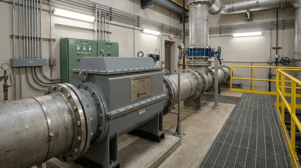
While open-channel grinding is common at headworks, many applications within the plant and lift stations require closed-piping solutions. This creates a specific demand for robust inline reduction technologies. However, selecting the right equipment is fraught with challenges, primarily due to the difficulty in balancing hydraulic throughput with particle size reduction. An incorrectly specified unit can become a bottleneck, inducing excessive head loss or failing to protect sensitive positive displacement pumps.
This article provides a rigorous technical analysis of the Top 10 Inline Grinder Manufacturers for Water and Wastewater commonly found in municipal and industrial specifications. Beyond a simple list, we will explore the engineering mechanics, selection criteria, and specification nuances required to integrate these units effectively into high-performance treatment systems. Whether retrofitting a sludge recirculation line or designing a new lift station, understanding the distinction between marketing claims and engineering reality is paramount for long-term reliability.
How to Select and Specify Inline Grinders
Specifying an inline grinder requires a multi-dimensional approach that goes beyond simply matching flange sizes. Engineers must evaluate the intersection of hydraulic constraints, material science, and mechanical design. The following criteria define the engineering baseline for selecting equipment from the Top 10 Inline Grinder Manufacturers for Water and Wastewater.
Duty Conditions & Operating Envelope
The operating envelope of an inline grinder is defined by more than just flow rate. Engineers must characterize the fluid rheology and solids burden accurately.
- Flow Rate vs. Head Loss: Unlike pumps where flow is the output, for grinders, flow is a constraint. The manufacturer’s curve must be analyzed to ensure the pressure drop (Delta P) at peak wet weather flow (PWWF) does not starve the downstream pump of Net Positive Suction Head (NPSH).
- Solids Loading: Specifications must distinguish between “occasional rags” (typical sewage) and “heavy sludge” (3-6% Total Solids). High solids concentrations require higher torque and lower rotational speeds to prevent binding.
- Pressure Rating: Inline units are pressure vessels. While standard housing may be rated for 50-90 psi, discharge-side applications often require ANSI 150# or 300# ratings. Engineers must verify the burst pressure of the seal housing, not just the cutter chamber.
Materials & Compatibility
The longevity of a grinder is directly tied to the metallurgy of the cutter stack and the shaft design.
- Cutter Hardness: Standard tool steel is often insufficient for grit-laden wastewater. Specifications should call for heat-treated alloy steel or tungsten carbide coated cutters with a hardness range of 45-60 HRC (Rockwell C).
- Shaft Geometry: Hexagonal shafts are preferred over keyed round shafts. Hex shafts distribute torque load evenly across the cutter faces, minimizing failure points associated with keyway fatigue.
- Housing Materials: Ductile iron is standard for municipal wastewater, but industrial or acidic applications (pH < 5) mandate 304 or 316 Stainless Steel housings to prevent corrosion-induced seal failure.
Hydraulics & Process Performance
The hydraulic profile of an inline grinder is the most overlooked aspect of specification.
- Open Area Ratio: This is the ratio of the open flow path through the cutter stack to the cross-sectional area of the inlet pipe. A low open area ratio results in high fluid velocities, increased wear, and significant head loss.
- Particle Size Control: Different downstream equipment requires different particle sizes. A centrifugal pump may tolerate 2-inch solids, while a spiral heat exchanger may require reduction to < 8mm. The "tooth count" and cutter cam design dictate the final particle size.
Installation Environment & Constructability
Physical constraints often dictate the feasibility of inline grinding retrofits.
- Pipeline Orientation: While many twin-shaft grinders can operate horizontally or vertically, the seal lubrication system must be compatible with the orientation. Vertical installations often require specific seal flush arrangements to prevent air entrapment in the seal chamber.
- Maintenance Access: The design must allow for the removal of the cutter cartridge without removing the entire body from the pipeline (“maintenance-in-place”) to minimize downtime and crane requirements.
Reliability, Redundancy & Failure Modes
Understanding how these machines fail is critical to designing a robust system.
- Shaft Deflection: Under heavy load, long shafts can deflect, causing cutters to clash. Intermediate shaft supports are required for high-flow, long-stack units.
- Seal Failure: This is the most common failure mode. Cartridge mechanical seals are superior to component seals for ease of replacement. Redundant sealing systems with barrier fluids provide the highest reliability.
- MTBF: In severe sludge applications, a Mean Time Between Failure of 3-5 years for the cutter stack is typical. Specifications should require guaranteed availability of cutter cartridges.
Controls & Automation Interfaces
The grinder controller is the brain of the protection system. Simple “on/off” control is insufficient.
- Jam Sensing Logic: The controller must monitor current (amperage). Upon detecting a spike (jam), it should stop, reverse to clear the obstruction, and retry.
- Progressive Logic: Advanced controllers will retry a set number of times (e.g., 3 times) before faulting out to protect the motor.
- SCADA Integration: The system must output status (Run, Fault, Reverse) and alarms to the central SCADA system via Modbus or Ethernet/IP for remote monitoring.
Maintainability, Safety & Access
- Cutter Cartridge vs. Individual Cutters: Individual cutters allow for partial replacement but are labor-intensive to restack. Cartridge designs allow for rapid swap-out of the entire element, reducing confined space entry time.
- Auto-Tensioning: Some manufacturers offer auto-tensioning of the cutter stack to compensate for wear, reducing the need for manual tightening intervals.
Lifecycle Cost Drivers
The purchase price is often only 30% of the lifecycle cost. Engineers must evaluate:
- Energy: High-torque, low-speed grinders are generally energy efficient, but hydraulic losses add indirect energy costs to the main pumps.
- Rebuild Costs: The cost of a “Cutter Exchange Program” (where the OEM swaps a refurbished cartridge for a worn one) should be factored into the 10-year OPEX analysis.
Comparison of Top Manufacturers and Technologies
The following tables provide an engineering comparison of the Top 10 Inline Grinder Manufacturers for Water and Wastewater. These comparisons focus on design philosophy, application suitability, and maintenance profiles rather than marketing features. Engineers should use these as a starting point for detailed specification development.
Table 1: Manufacturer & Technology Profile
| Manufacturer | Core Technology | Primary Strengths | Typical Applications | Maintenance Profile |
|---|---|---|---|---|
| JWC Environmental (Sulzer) |
Twin-Shaft Low Speed High Torque | Market ubiquity; extensive cutter options (Wipes Ready); high flow capabilities. | Raw sewage pump stations, sludge lines, prison waste. | Cartridge/stack exchange programs widely available. |
| Franklin Miller (Taskmaster) |
Twin-Shaft / Cartridge | “Cutter Cartridge” monolithic design reduces stack loosening; robust shafting. | Headworks, inline sludge, septage receiving. | Cartridge design simplifies field replacement but requires OEM parts. |
| Vogelsang (XRipper) |
Twin-Shaft / Monolithic | Monolithic Ripper rotors (single piece) eliminate stack tightening; extremely easy onsite maintenance. | Sludge recirculation, biogas plants, inline sewage. | Rotor replacement is fast; minimal individual parts to manage. |
| Netzsch (N.Mac) |
Twin-Shaft | Integrated seamlessly with PC pumps; shock absorption systems for hard solids. | Sludge feed to dewatering, digester recirculation. | Designed for modular maintenance; cutters replaceable without full disassembly. |
| Börger (Multichopper/Unihacker) |
Macerator & Twin-Shaft | MIP (Maintenance in Place) design; reversible cutting plates; adjustable tension. | Biogas substrates, sludge thickening, sensitive pump protection. | Quick-release covers allow rapid access to wear parts. |
| SEEPEX (Macerator) |
Inline Macerator | Designed specifically to protect Progressive Cavity pumps; integrated control logic. | Dewatering feed, thickened sludge, polymer injection protection. | Headplate and cutter replacement is straightforward inline. |
| Landia (BioChop/Macerator) |
Knife-Gate / Chopper | Known for aggressive chopping pumps, their inline units focus on heavy slurry and ag-waste crossover. | Heavy sludge, digester mixing loops, lift stations. | External knife adjustment systems available on some models. |
| Mono (NOV) (Muncher) |
Twin-Shaft | Slow speed; proprietary cutter geometry for fine grinding; energy efficient. | Small to medium lift stations, packaged plants. | Standard individual cutter stack design; reliable performance history. |
| Hydro-Dyne (Shark) |
Twin-Shaft | Heavy-duty construction; custom fabrication capabilities for tight spaces. | Headworks screening bypass, septage receiving stations. | Uses standard bearing and seal arrangements for serviceability. |
| Wangen (X-Unit) |
Foreign Object Separator + Cutting | Combines stone/heavy object separation with cutting; protects against catastrophic damage. | Biogas, difficult industrial wastewater, manure processing. | Split process: removal of non-grindables first, then cutting. |
Table 2: Application Fit Matrix
| Application Scenario | Primary Constraint | Best-Fit Technology | Why? | Key Spec Requirement |
|---|---|---|---|---|
| Raw Sewage Lift Station (Pump Protection) |
High Flow / Ragging | Twin-Shaft (Channel or Inline) | Must pass high volume of liquid while shredding wipes. | Low Head Loss Design (< 1 PSI clean) |
| Sludge Recirculation (Digester) |
High Solids / Viscosity | Twin-Shaft or Macerator | Thick sludge requires high torque; hair/fiber needs shearing. | Hex shafting; Hardened cutters (>55 HRC) |
| Centrifuge/Press Feed (Dewatering) |
Particle Size Control | Macerator (Perforated Plate) | Needs uniform small particle size to prevent nozzle clogging. | Defined output size (e.g., < 5mm) |
| Septage Receiving (Truck Unloading) |
Rocks / Debris | Twin-Shaft with Rock Trap | Rocks will destroy cutters; separation is required. | Integrated heavy object trap |
| Small Package Plant (Inlet) |
Budget / Space | Comminutor / Single Shaft | Lower duty cycle; smaller footprint. | Simple controls; single-phase power option |
Engineer and Operator Field Notes
Theory often diverges from reality in the field. The following notes are compiled from commissioning experiences and long-term operational feedback involving the Top 10 Inline Grinder Manufacturers for Water and Wastewater.
Commissioning & Acceptance Testing
During the Factory Acceptance Test (FAT) and Site Acceptance Test (SAT), vigilance is required.
- Rotation Logic Check: Do not assume the “Reverse” function works. Physically witness the shafts stop and reverse direction upon simulated jam. Verify the time delay between forward-stop-reverse to prevent high current inrush from damaging the VFD or starter.
- Dry Run Limits: Most inline grinders rely on the process fluid for seal lubrication. Ensure the contractor does not dry-run the unit for rotation checks for more than a few seconds, or seal faces may crack due to thermal shock.
- Amp Draw Baseline: Record the amperage draw with clean water. This establishes the baseline “no-load” condition. Future maintenance decisions will be based on deviations from this baseline.
O&M Burden & Strategy
Maintenance strategies for inline grinders fall into two categories: proactive and reactive. Reactive maintenance usually results in sewage spills. A proactive approach includes:
- Cutter Stack Tightening: For designs with individual cutters, the stack will loosen over time due to vibration and wear. A loose stack allows cutters to wobble, damaging the hex shaft. Schedule a torque check annually.
- Seal Inspection: Inspect the seal chamber barrier fluid (if applicable) monthly. Milky fluid indicates water intrusion; low fluid indicates a leak to the process.
- Spare Parts Inventory: If you do not have a redundant channel/grinder, a spare cutter cartridge is a mandatory shelf item. Lead times for new cartridges can exceed 8-12 weeks.
Troubleshooting Guide
- Symptom: Frequent Reversing (Ghost Jams).
Root Cause: Often caused by soft rags wrapping around the shaft rather than a hard object. Alternatively, the amperage trip setpoint may be too close to the running amperage.
Solution: Inspect the stack for wrapping. If clean, adjust the PLC jam timer delay slightly to allow momentary spikes to pass. - Symptom: Excessive Noise/Vibration.
Root Cause: Bearing failure or a bent shaft.
Solution: Perform a vibration analysis. If the frequency matches the shaft speed (1x RPM), it is likely imbalance or a bent shaft. If high frequency, suspect bearings.
Design Details and Calculations
Proper integration of an inline grinder requires specific hydraulic calculations. Ignoring these can lead to system bottlenecks.
Sizing Logic & Methodology
Do not size based on pipe diameter. Size based on peak flow velocity and head loss.
- Determine Peak Wet Weather Flow (PWWF): This is your critical design point.
- Calculate Velocity: Calculate the fluid velocity through the grinder open area (not the flange area).
V = Q / A_open
Velocity should generally be kept below 6-8 ft/s to prevent excessive head loss and abrasive wear. - Check Head Loss (Bernoulli): Consult the manufacturer’s specific curve. Ensure that at PWWF, the head loss does not reduce the suction pressure at the pump below the NPSHr + Safety Margin (usually 2-3 ft).
Specification Checklist
When writing the RFP, ensure these line items are included to secure a high-quality unit from the Top 10 Inline Grinder Manufacturers for Water and Wastewater:
- Cutter Material: Specify “Heat-treated alloy steel, surface hardened to minimum 45-50 HRC” or “Tungsten Carbide.”
- Shaft Construction: “Hexagonal shafting with tensile strength exceeding 150,000 psi.”
- Seal Configuration: “Cartridge-style mechanical seals rated for 1.5x maximum system pressure.”
- Controller: “NEMA 4X enclosure with PLC-based jam sensing, auto-reverse, and fail-safe alarm contacts.”
- Testing: “Manufacturer to provide certified head loss curves based on water testing.”
Standards & Compliance
- NEC / NFPA 70: If the grinder is located in a screen room or wet well, the motor and cabling must likely be rated Class 1, Division 1 or 2 (Explosion Proof).
- IP Ratings: For washdown environments, IP68 (submersible) motors are preferred even for dry-pit installations to protect against accidental flooding.
- AWWA: While there is no specific AWWA standard solely for grinders, general equipment standards for coating and materials (ASTM) apply.
Frequently Asked Questions
What is the difference between an inline grinder and a macerator?
While often used interchangeably, “inline grinder” typically refers to twin-shaft slow-speed units that use counter-rotating cutters to shred solids. These handle high flows and tough solids like wipes and wood. A “macerator” often refers to a unit with a perforated plate and a rotating cutting blade (similar to a meat grinder). Macerators provide a finer, more consistent particle size but generally have higher head loss and are better suited for sludge or lower-flow applications.
How do you calculate head loss for an inline grinder?
Head loss cannot be calculated using standard pipe friction formulas because the geometry is complex. It must be derived from the manufacturer’s empirical data curves, usually plotted as Flow (GPM) vs. Head Loss (Inches of Water or PSI). Factors influencing this include the cutter tooth profile, the open area ratio, and the viscosity of the fluid. Always request a curve adjusted for your specific solids concentration.
How often do cutter stacks need to be replaced?
Cutter life varies heavily by application. In standard municipal raw sewage, cutter stacks typically last 5 to 7 years. In abrasive environments (high grit) or heavy sludge applications, life may be reduced to 2 to 4 years. Using tungsten carbide cutters can extend life significantly in abrasive applications but increases the initial capital cost.
What is the best way to prevent grinder jamming?
The primary defense is a robust Auto-Reverse controller. When a hard object is encountered, the current spikes, and the unit reverses to reposition the object. However, the best prevention is upstream protection. Installing a rock trap or coarse screen before the grinder prevents non-grindables (rocks, masonry) from reaching the cutters, which is the leading cause of fatal jams.
Can inline grinders be installed vertically?
Yes, most of the Top 10 Inline Grinder Manufacturers offer units capable of vertical installation. However, this must be specified during ordering. Vertical units often require different seal flushing arrangements to prevent air pockets from forming in the upper seal housing, which would lead to dry running and seal failure.
How much does a municipal inline grinder cost?
Costs vary by size and materials. A small 4-inch pipeline grinder for a package plant might range from $15,000 to $25,000. A large 12-inch or 16-inch unit for a main lift station can range from $60,000 to $120,000 depending on control complexity, explosion-proof ratings, and cutter materials. Installation and electrical integration are separate costs.
Conclusion
KEY TAKEAWAYS
- Hydraulics First: Never ignore head loss. Ensure the grinder does not starve downstream pumps.
- Application Matters: Use twin-shaft grinders for raw sewage and wipes; use plate macerators for defined particle size in sludge/dewatering.
- Material Selection: Specify hex shafts and hardened alloy or tungsten cutters for longevity.
- Control Logic: Auto-reverse logic is mandatory for protecting the motor and clearing soft jams.
- TCO Approach: Evaluate the cost of replacement cartridges over 10 years, not just the initial bid price.
Selecting the right equipment from the Top 10 Inline Grinder Manufacturers for Water and Wastewater is a critical engineering task that directly impacts plant reliability. The market offers a range of technologies, from the ubiquitous twin-shaft designs of JWC and Franklin Miller to the maintenance-friendly monolithic rotors of Vogelsang and the precision macerators of SEEPEX and Netzsch.
For the specifying engineer, the goal is to match the machine’s mechanical limitations with the fluid’s hydraulic reality. By focusing on open area ratios, seal technology, and ease of maintenance access, engineers can design systems that protect expensive downstream assets without becoming maintenance nightmares themselves. When in doubt, prioritize manufacturers who provide transparent head loss data and offer robust local support for cutter cartridge exchange programs.