
Rotork Controls vs VAG
Introduction
The interface between a valve and its control mechanism remains one of the most frequent points of failure in modern water and wastewater treatment plants. A substantial share of reported “valve failures” are actually actuation or interface failures—issues with sizing, mounting, signal loss, or power delivery—rather than a failure of the pressure boundary itself. For municipal engineers and plant directors, the decision often boils down to a conflict of philosophies: do you standardize on a single actuation platform across the plant, or do you accept the valve manufacturer’s integrated package?
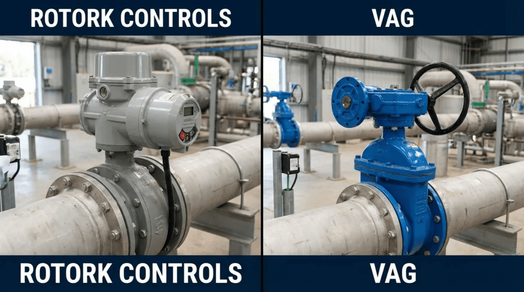
To clarify the engineering context: Rotork is a global leader in intelligent actuation and flow control networks, typically supplied as a separate component to be mounted on various valves. VAG is a manufacturer of heavy-duty valves, such as the RIKO plunger valve and EKN butterfly valve, which often supplies turnkey solutions including its own or third-party actuation. The engineering challenge lies in deciding whether to specify a VAG valve with a Rotork actuator, taking a best-of-breed component approach, or a complete VAG solution with single-source responsibility.
This decision impacts everything from construction sequencing to twenty-year lifecycle costs. A mismatch between the actuator’s capabilities and the valve’s dynamic torque requirements can lead to premature stem wear, motor burnout, or water hammer events. This article guides engineers through the technical nuances of that decision, focusing on heavy-duty applications in municipal water distribution, dams, and wastewater treatment plants.
A note on the framing, since the title invites a misreading. Rotork and VAG are not competitors. Rotork manufactures actuators; VAG manufactures valves. A VAG valve fitted with a Rotork actuator is an entirely ordinary and widely installed combination, not a compromise between two rivals. Anyone arriving here expecting a head-to-head product comparison should understand that the real decision is a procurement strategy question: buy the valve and the actuator separately and take responsibility for the interface yourself, or buy an integrated package and transfer that responsibility to the valve supplier. The article below addresses that question, which is the useful one.
Two practical consequences follow. First, an actuator comparison belongs against other actuator manufacturers — see our guide to Rotork and AUMA actuators, which is a genuine head-to-head. Second, a valve comparison belongs against other valve manufacturers. For VAG’s own product range, see our guide to VAG valves, and for the wider field, our roundups of valve construction service manufacturers and valve service manufacturers.
Corporate ownership in the European valve sector has changed hands repeatedly in recent years. Verify VAG’s current ownership and North American representation directly before writing the name into a specification.
How to Select and Specify: The Engineering Criteria
When evaluating flow control solutions, engineers must look beyond the catalog data sheet. The selection process involves analyzing how the actuator interacts with the valve under varying hydraulic conditions.
Duty Conditions & Operating Envelope
- Isolation vs. Modulation: If the application is simple open/close isolation, a standard valve with a basic electric actuator is sufficient. However, for flow control requiring continuous modulation, the distinction becomes critical. Rotork’s modulating ranges offer high-resolution positioning. VAG’s control valves have non-linear torque curves. The specifier must ensure the selected actuator can handle the dynamic torque changes as the plunger moves through the flow stream.
- Thrust and Torque Requirements: Large diameter butterfly and plunger valves can generate substantial seating and unseating torques. A common mistake is sizing the actuator based on break torque without accounting for running torque in high-velocity flows. Actuators are sized from comprehensive torque maps, but accurate input data from the valve manufacturer is required.
- Speed of Operation: Rapid closure prevents reservoir drainage but risks water hammer. VAG provides hydraulic damping solutions on their lever-arm valves. Rotork offers variable speed electric actuation. The engineer must decide whether surge protection should be mechanical or electronic.
Materials & Compatibility
- Enclosure Ratings: Rotork is known for its double-sealed enclosure design, which protects internal electronics even if the terminal cover is removed in a wet environment. Actuators supplied within an integrated valve package may vary depending on the OEM partner used for a specific project.
- Coating Standards: Specifications should reference ISO 12944. VAG valves typically come with heavy-duty GSK-certified epoxy coatings suitable for potable water and wastewater. The actuator mounted on top must match this durability. In a mixed assembly, ensure the mounting kit is stainless steel to prevent galvanic corrosion at the interface.
Hydraulics & Process Performance
Hydraulic performance is dictated by the valve geometry. Plunger valves are engineered to manage cavitation during high-pressure drops. However, the actuator controls the rate of that pressure drop.
- Linearity: A linear signal from the SCADA system does not always equal a linear flow change. Intelligent actuators can be programmed with custom characterization curves to linearize the flow output of a butterfly valve. This feature often eliminates the need for complex PLC programming.
Installation Environment & Constructability
- Orientation: Large valves may require horizontal installation of the stem. Actuators have oil-bath lubrication systems that may need reconfiguration for non-vertical mounting.
- Retrofitting: In rehabilitation projects, actuator manufacturers specialize in retrofitting onto existing valves without removing them from the line. This capability often makes an independent actuator the preferred choice for plant upgrades where the pressure boundary remains intact.
Reliability, Redundancy & Failure Modes
Pro Tip: Define the loss-of-signal and loss-of-power positions explicitly.
- Fail-Safe Requirements: VAG offers weighted hydraulic actuators providing mechanical fail-safe closure without electricity. Rotork offers electro-hydraulic or battery and capacitor backup options. For critical dam safety or pump discharge applications, the mechanical reliability of a weighted arm is often preferred over a battery-dependent system.
- Diagnostic Capability: Intelligent actuator data logging tracks torque trends over time. If a valve seat begins to swell or degrade, the actuator detects the torque increase and alerts operators before failure occurs.
Controls & Automation Interfaces
- Networks: Rotork promotes Pakscan, a loop network designed for long distances in water plants. Integrated valve packages generally rely on standard open protocols such as Profibus, Modbus, and EtherNet/IP.
- Standardization: A plant manager often wants one interface for all valves. If the plant has dozens of actuators from one manufacturer, buying a valve package with a different actuator brand complicates SCADA integration and spare parts inventory.
Lifecycle Cost Drivers
- Capital Cost: An integrated valve package is often cheaper initially than buying a bare valve plus a separate actuator, mounting kit, and assembly labor.
- Operating Cost: Standardizing on one actuator platform reduces training costs and spare parts inventory. However, integrated hydraulic solutions often last longer in high-cycle applications than electromechanical gear trains.
Comparison Tables
The following tables compare the two primary approaches: the intelligent electric actuator approach and the integrated valve solution approach.
| Feature / Criteria | Independent Actuation (Rotork) | Integrated Valve Solution (VAG) |
|---|---|---|
| Primary Focus | Intelligent actuation, data logging, and plant-wide control networks. | Hydraulic integrity, valve longevity, and specific flow characteristics. |
| Best-Fit Application | Plant-wide automation standards, difficult access areas requiring remote diagnostics, complex modulation logic. | Pump discharge control, dam bottom outlets, high-velocity pressure regulation, fail-safe gravity closure. |
| Control Interface | Advanced digital protocols with non-intrusive setting tool. | Dependent on the specific actuator supplied, or hydraulic control panels for lever-arm valves. |
| Fail-Safe Mechanism | Battery backup, supercapacitor, or electro-hydraulic. | Mechanical drop-weight or hydraulic accumulator. Highly reliable for emergency shutdown. |
| Maintenance Profile | Electronics-focused. Battery changes, firmware updates, software diagnostics. | Mechanical and hydraulic focused. Seal replacement, hydraulic fluid management, cylinder maintenance. |
| System Responsibility | Actuator only. Interface responsibility falls to the integrator or contractor. | Single-source. The valve manufacturer warrants sealing and actuation performance as a unit. |
| Application Scenario | Recommendation | Engineering Rationale |
|---|---|---|
| Wastewater Treatment (Headworks/Aeration) | Independent actuation on VAG valves | Aeration requires precise modulation. Positioning accuracy and feedback loops are superior for process control. Standardization simplifies O&M. |
| Pump Discharge Check/Control | Integrated hydraulic solution | Requires managed opening and closing times to prevent surge. Lever-arm hydraulic damper systems offer mechanical tuning that is safer than relying on backup power. |
| Dam Bottom Outlet / Safety Valve | Plunger valve with integrated hydraulics | Extreme velocities and cavitation risk. The actuator must be integral to the valve design to handle vibration and massive torque loads. |
| Water Distribution Network (Buried Service) | Gate valve with manual or electric actuation | If automated, IP68 actuators are ideal for pits liable to flooding. If manual, a rugged gearbox is sufficient. |
Engineer & Operator Field Notes
Commissioning & Acceptance Testing
The handshake between the actuator and the valve is the most critical phase of commissioning.
- Setting End Stops: When commissioning an actuator on a wedge gate valve, specify torque seating for the closed position and position limit for the open position. Torque seating ensures a tight seal even as the valve wears. However, for resilient-seated butterfly valves, always use position limits for both open and close to avoid jamming the disc into the liner.
- Direction of Rotation: Ensure the actuator is configured to match the valve gearbox. Mismatches can result in the actuator shearing the valve stem or keyway during the first stroke.
- The Hunting Phenomenon: In modulating applications, if the deadband settings are too tight and the hydraulic system has noise, the valve will oscillate, causing motor overheating. Adjust the deadband to match the process reality, not the theoretical ideal.
Specifying a named valve with a named actuator “or approved equal” often leads to a contractor supplying the valve with a cheaper, less capable actuator brand to save margin. If plant standardization relies on specific diagnostic software or handheld setting tools, the “or equal” clause must explicitly exclude actuators that do not meet these interface standards.
O&M Burden & Strategy
- Intelligent Actuator Ecosystem: Operators need training on the specific setting tool. The advantage is that settings can be downloaded and cloned to a replacement unit instantly. Maintenance is minimal but involves battery management.
- Integrated Hydraulics: Maintenance involves checking oil levels, filter changes on hydraulic power units, and inspecting cylinder seals. While more mechanical labor is involved, it is often within the skill set of general plant mechanics, whereas electronic diagnostics may require electrical technicians.
Troubleshooting Guide
- Torque Trip Alarms: If an actuator trips on torque in mid-travel, it usually indicates debris in the valve or a lack of lubrication on the stem nut. Use the actuator data log to see where in the stroke the torque spike occurred.
- Valve Drifting: If a hydraulic control valve drifts from its setpoint, check the solenoid valves or internal leakage in the hydraulic cylinder. If an electric actuator drifts, it is almost certainly a control signal issue or a declutch lever not fully engaged.
Design Details and Calculations
Sizing Logic & Methodology
Never rely solely on the valve’s break torque. You must calculate against the Maximum Allowable Stem Torque (MAST).
Step 1: Determine valve torque demand. Ask the valve manufacturer for the torque curve at the specific differential pressure. Note that dynamic torque from hydrodynamic forces on the disc can sometimes exceed seating torque in butterfly valves.
Step 2: Select actuator torque. Apply a safety factor, typically 1.3 to 1.5 times the valve torque demand. Do not oversize excessively. If actuator stall torque exceeds the MAST of the valve shaft, you risk twisting the shaft if the valve jams.
Step 3: Check inertia and speed. For electric actuators, motor inertia can drive the valve tightly into the seat. Lost-motion hammerblow capability helps unseat sticky valves, but this impact load must be compatible with the valve keyway design.
Specification Checklist
- Mounting Flange: Must strictly adhere to ISO 5211 for part-turn valves or ISO 5210 for multi-turn valves.
- Drive Bushing: Specify who machines the drive bushing, the interface between actuator and stem. Ideally the actuator supplier provides the bushing unmachined, or the valve manufacturer machines it to fit their stem.
- Coating Protocol: Ensure the mounting bracket coating matches the valve body.
- Factory Acceptance Test: Require the actuator to be mounted on the valve at the factory for the FAT. Do not accept separate testing. The combined unit must be tested for seating, unseating, and modulation hysteresis.
Who Owns the Interface Failure
The single most consequential difference between the two procurement routes is rarely discussed at design stage: when the assembled unit does not work, who fixes it?
With an integrated package, the valve manufacturer has warranted the combination and owns the problem. With separately purchased components, the responsibility chain fragments. The actuator manufacturer will demonstrate that the actuator produces its rated torque. The valve manufacturer will demonstrate that the valve requires no more than its published torque. Both will be correct, and the utility will still have a valve that will not seat, because the failure lives in the bracket, the drive bushing machining, the keyway fit, or the limit settings — none of which either party supplied.
Three specification provisions prevent this:
- Name one party as responsible for the assembled unit in the contract documents, whether that is the valve supplier, the actuator supplier, or the contractor. Do not leave it implied.
- Require factory assembly and testing of the combination, not of the components separately. A valve tested in Germany and an actuator tested in England prove nothing about the pair.
- Require the drive bushing to be machined by whoever also holds the stem drawing, and require the machined fit to be verified at the factory acceptance test.
Standards & Compliance
- AWWA C542: Electric Motor Actuators for Valves and Slide Gates.
- AWWA C504: Rubber-Seated Butterfly Valves, covering the valve performance.
- ISO 5210 / ISO 5211: Multi-turn and part-turn valve actuator attachments.
- NEMA 250 / IEC 60529: Enclosure ratings. NEMA 6P or IP68 is recommended for water applications.
Frequently Asked Questions
How do you select the correct actuator for a plunger valve?
Selection requires matching the multi-turn or quarter-turn requirement of the valve gearbox. Plunger valves typically operate via a multi-turn input shaft into a gearbox. You must obtain the input torque and total turns from the valve manufacturer. Select a multi-turn actuator that provides the required torque with an appropriate safety factor, while ensuring the actuator’s output speed allows for the desired full-stroke time without causing water hammer.
Can actuators be retrofitted onto existing valves?
Yes, this is a common application. The critical engineering task is designing the adaptation kit to bridge the ISO flange on the actuator to the existing bonnet or gearbox flange of the valve. Measurements of the stem diameter, keyway, and bolt circle are required to fabricate a custom mounting kit.
What is the typical lifecycle cost difference between electric and hydraulic actuation?
Electric actuation typically has a lower lifecycle cost for standard modulation and isolation duties due to lower maintenance requirements, with no oil changes, filters, or hydraulic leaks. However, for very large valves or high-speed safety shutoff applications, hydraulic solutions may offer lower total ownership costs by eliminating the need for large electric backup systems and providing simpler mechanical longevity.
Why does my actuator show a torque fault on a butterfly valve?
This often occurs due to stiction after the valve has been stationary for long periods, or undersizing during specification. Butterfly valves can develop high unseating torques. If the actuator torque setting is too low, or if the torque boost feature is not enabled for the unseating movement, the actuator will trip to protect the motor. Verify the actual valve torque against the actuator’s rated output.
When should I specify a weighted hydraulic lever over an electric actuator?
Specify a weighted hydraulic drop-weight system for critical pump discharge check valves or dam safety valves where fail-safe closure is required regardless of power availability. While battery fail-safe options exist, the potential energy of a gravity-driven weight provides a level of reliability and closure force preferred in catastrophic power failure scenarios.
Conclusion
Key Takeaways for Engineers
- Define the Interface: The mounting kit and drive bushing are the most common points of failure in mixed-vendor assemblies. Specify materials and machining tolerances strictly.
- Standardization vs. Performance: Choose an independent actuator platform if your priority is a unified plant-wide control network and detailed diagnostics. Choose a complete valve package if the hydraulic application is complex.
- MAST Matters: Always calculate the Maximum Allowable Stem Torque. A powerful actuator can destroy a valve stem if end stops are not set correctly.
- Process Duty: For high-frequency modulation, electric resolution is superior. For safety-critical fail-safe, hydraulic drop-weights are hard to beat.
- Single Source Responsibility: If you separate the purchase, you as the engineer are responsible for the integration. Ensure your specifications cover the factory acceptance test of the combined unit.
The decision is not a binary choice of better or worse, but a strategic selection based on application criticality, maintenance philosophy, and hydraulic requirements. Rotork represents intelligent control and data visibility. VAG represents hydraulic reliability for moving large volumes of water safely.
For the consulting engineer, the best path is often a hybrid approach: standardization on one actuator platform for the majority of isolation and control valves to streamline O&M, while deferring to integrated hydraulic packages for specialized, high-risk applications such as pump check valves and turbine bypass systems.