Non-Clog Wastewater Pumps Wet Well Design and Minimum Submergence to Prevent Vortexing
Introduction
One of the most persistent and costly failures in municipal wastewater collection systems is not the mechanical failure of the pump itself, but the failure of the intake hydraulics. Engineers frequently specify high-efficiency, robust pumping equipment, only to place it into a geometry that guarantees reduced lifespan. A significant percentage of premature bearing failures, vibration issues, and capacity reductions are directly attributable to poor Non-Clog Wastewater Pumps Wet Well Design and Minimum Submergence to Prevent Vortexing. While the pump is the active component, the wet well is the environment that dictates its survival.
This challenge is prevalent in both municipal lift stations and industrial wastewater sumps, particularly where retrofits increase flow requirements within existing, constrained footprints. The consequences of neglecting proper intake design include air entrainment, which leads to impeller imbalance; cavitation, which erodes hydraulic surfaces; and pre-swirl, which alters the pump’s head-capacity curve unpredictably. For consulting engineers and utility directors, understanding the physics of the wet well is as critical as understanding the pump curve.
Often, the focus during the design phase is heavily weighted toward the static head, friction losses, and force main trajectory. However, the fluid dynamics entering the pump—specifically the approach velocity and the suppression of surface and subsurface vortices—are often relegated to standard details or rules of thumb that may no longer apply to modern high-specific-speed impellers. This article aims to bridge the gap between theoretical hydraulics and practical station design, helping engineers optimize Non-Clog Wastewater Pumps Wet Well Design and Minimum Submergence to Prevent Vortexing to ensure long-term reliability and reduced operational expenditure.
How to Select and Specify for Hydraulic Integrity
Designing a reliable pumping station requires a holistic view where the civil structure and the mechanical equipment are treated as a unified system. The specification of the wet well geometry and the pump placement must occur simultaneously. The following criteria outline the engineering decisions necessary to achieve optimal performance.
Duty Conditions & Operating Envelope
The first step in proper design is establishing the complete operating envelope. While peak flow dictates the discharge pipe sizing, minimum flows often dictate the wet well health.
- Variable Flow Rates: With the prevalence of Variable Frequency Drives (VFDs), pumps operate across a wide range of speeds. The wet well design must prevent solids deposition at low flows while preventing vortex formation at peak flows.
- Specific Speed (Ns): Higher specific speed pumps are more sensitive to intake hydraulic anomalies. Engineers must calculate Ns early in the design to determine the required conservatism of the intake structure.
- Approach Velocity: The velocity of the wastewater approaching the pump intake is critical. The Hydraulic Institute (HI) Standard 9.8 recommends an approach velocity of 2 to 5 ft/s (0.6 to 1.5 m/s) to prevent solids settling while maintaining uniform flow.
Materials & Compatibility
The physical structure of the wet well interacts chemically and mechanically with the wastewater.
- Surface Roughness: Concrete roughness can affect flow boundary layers. In critical applications, specifications may require smooth-troweled finishes or epoxy coatings to minimize friction and turbulence near the intake.
- Corrosion Resistance: In environments with high hydrogen sulfide (H2S), concrete corrosion (biogenic sulfide corrosion) alters the geometry over time. This degradation can change clearances and flow patterns. Specify acid-resistant coatings (e.g., PVC liners or high-build epoxies) to maintain the designed geometry throughout the plant lifecycle.
- Fillet Construction: To prevent solids accumulation in corners (which can lead to septic conditions and gas release), fillets (benchings) are required. These are typically concrete, but in retrofits, stainless steel or polymer baffles may be used.
Hydraulics & Process Performance
This is the core of Non-Clog Wastewater Pumps Wet Well Design and Minimum Submergence to Prevent Vortexing. The primary goal is to deliver a uniform velocity distribution to the impeller eye.
- NPSH Available (NPSHa): While submersible pumps typically have positive head on the suction, the local pressure drop at the eye of the impeller due to a vortex can simulate a drop in NPSHa, leading to cavitation. Design calculations must account for the vapor pressure of the wastewater at maximum summer temperatures.
- Pre-Swirl: Wastewater entering the pump should not have significant rotation. Bulk rotation in the wet well changes the angle of attack on the impeller vanes, potentially shifting the operating point along the curve or causing flow separation.
- Vortex Types: Designs must mitigate both Type 1/2 surface vortices (swirls) and Type 3+ vortices (dye core to air entrainment). Subsurface vortices, which originate from the floor or walls, are equally damaging but invisible from the surface.
Installation Environment & Constructability
Theoretical designs must be constructible in the field.
- Trench-Type Wells: For high-capacity stations, a self-cleaning trench-type wet well is often superior to a circular well. However, this requires specific excavation and forming. Engineers must assess the geotechnical feasibility of deep rectangular excavations versus caisson-sunk circular wet wells.
- Baffle Walls: To straighten flow, baffle walls may be necessary. Ensure these are designed with structural reinforcement to withstand hydraulic surges and are accessible for cleaning.
- Splitter Vanes: In circular wet wells, a floor-mounted flow splitter beneath the pump inlet is often required to stop floor vortices. Specify these as integral to the installation kit or cast-in-place.
Reliability, Redundancy & Failure Modes
Understanding how the system fails allows for better defensive design.
- Air Entrainment: Entrained air as low as 2-4% can significantly reduce pump efficiency. Higher levels can cause air binding, where the pump loses prime despite being submerged. This is a common failure mode when minimum submergence levels are violated during draw-down cycles.
- Vibration: Hydraulic instability causes low-frequency vibration. Over time, this fails mechanical seals and bearings. The design specification should include vibration limits (per HI 9.6.4) and requirement for baseline testing.
- Redundancy Sizing: When designing for N+1 redundancy, ensure the wet well hydraulic design accounts for the “worst-case” scenario of adjacent pumps running while one is idle, which can create stagnant zones or cross-flow turbulence.
Controls & Automation Interfaces
The control strategy is the software enforcement of the hydraulic design.
- Level Setpoints: The “Pump Off” elevation must be physically located above the calculated minimum submergence level. This is non-negotiable. Engineers should specify a “Low Level Alarm” and a “Low-Low Level Cutout” (hardwired) to protect the equipment.
- Cleaning Cycles: Modern VFD controllers often include “cleaning cycles” or “snore cycles” where the pump runs at full speed to flush solids. These cycles must be carefully programmed to ensure they do not draw the level down far enough to induce severe vortexing.
Maintainability, Safety & Access
Operators must be able to maintain the structure without excessive risk.
- Confined Space Entry: Complex baffling systems can create dangerous confined spaces. Designs should prioritize self-cleaning geometries (sloped floors 45 degrees or greater) to minimize the need for manual wash-downs.
- Grit Removal: All wastewater contains grit. The wet well design must facilitate grit transport to the pump intake or provide a dedicated sump for vacuum truck extraction.
Lifecycle Cost Drivers
The economic impact of wet well design extends far beyond the concrete pour.
- Energy Efficiency: A pump operating with pre-swirl or air entrainment operates off its best efficiency point (BEP). This can result in 5-10% higher energy consumption over the life of the station.
- Component Life: Proper hydraulic design can double the Mean Time Between Failures (MTBF) for wet-end components by eliminating cavitation-induced erosion and vibration-induced bearing fatigue.
Comparison of Wet Well Configurations and Application Fit
The following tables provide a structured comparison of common wet well geometries and their suitability for different wastewater applications. Engineers should use these to align the civil design with the hydraulic requirements of the project.
| Geometry Type | Hydraulic Features | Best-Fit Applications | Limitations & Risks | Maintenance Profile |
|---|---|---|---|---|
| Circular Wet Well | Symmetrical structure; susceptible to bulk rotation (swirling) without baffles. | Small to medium municipal lift stations; Package lift stations. | Risk of pre-swirl is high. Requires precise pump spacing. Not ideal for large capacity pumps (>3000 GPM). | Moderate. Solids tend to settle in the center or periphery if floor is flat. Fillets are essential. |
| Rectangular Wet Well | Easier to baffle; linear flow path. | Medium to large stations; Stations with bar screens/conveyors. | Dead zones in corners are common. Requires benching/fillets to prevent septic sludge buildup. | High. Corners collect grease and solids. Requires frequent wash-down if not properly benched. |
| Trench-Type (Self-Cleaning) | High velocity in trench prevents settling; highly uniform inlet flow (HI 9.8 preferred). | Large capacity terminal pumping stations; Stormwater stations; High solids loading. | Higher construction cost due to complex formwork. Requires specific cleaning ramp design. | Low. Design is inherently self-cleaning. Solids are continuously suspended and pumped out. |
| Confined Intake (Formed Suction) | Directs flow directly into pump eye; isolates pumps hydraulically. | Very large stations; Screw centrifugal pumps; Critical process feeds. | High capital cost. Difficult to access for blockage removal. | Moderate/High. If clogging occurs, access is difficult. Excellent hydraulic performance otherwise. |
| Application Scenario | Flow Regime | Key Design Constraint | Rec. Submergence Strategy | Relative Cost impact |
|---|---|---|---|---|
| Municipal Collection (Subdivision) | Intermittent; Low flow periods common. | Solids deposition during long dwell times. | Standard HI 9.8 calculation. Focus on fillet slope (1:1) to minimize residual volume. | Low |
| Master Lift Station (Terminal) | Continuous; Variable flow (VFD). | Vortexing at peak flow; Cavitation risk. | Conservative (1.2x – 1.5x HI min). CFD modeling recommended to verify intake conditions. | High |
| Stormwater / CSO | Extreme intermittency; High volume. | Rapid drawdown; Massive solids load. | Critical submergence control needed. Use anti-vortex plates to allow lower drawdowns. | Medium |
| Industrial Effluent | Continuous; Potential thermal issues. | Temperature vapor pressure (NPSHa); Chemical foam. | Increased submergence to counteract vapor pressure. Surface baffling to manage foam. | Medium |
Engineer & Operator Field Notes
Successful implementation of Non-Clog Wastewater Pumps Wet Well Design and Minimum Submergence to Prevent Vortexing requires bridging the gap between the design desk and the field. The following notes are compiled from commissioning experiences and operational realities.
Commissioning & Acceptance Testing
Verifying the hydraulic design during commissioning is often overlooked. Standard drawdown tests confirm capacity, but they do not confirm hydraulic quality.
- Visual Inspection: If possible, observe the water surface at peak flow (before the station goes live with sewage). Look for organized swirls. A momentary surface dimple is acceptable; a coherent swirl that persists is not.
- Vibration Baselines: Record vibration signatures at minimum submergence and maximum flow. If vibration spikes significantly as the water level drops to the “off” setpoint, the submergence is insufficient, or a vortex is forming.
- Aeration Check: Listen to the discharge piping. A crackling sound (like gravel) often indicates cavitation, but random bursts of noise can indicate air slugs passing through the system due to vortex entrainment.
Common Specification Mistakes
Engineers frequently inadvertently compromise hydraulic performance through ambiguous specifications.
- “Verify in Field”: Leaving the wet well dimensions or baffle locations to be “verified in field” by the contractor often leads to optimal construction ease rather than optimal hydraulics. Define these strictly on the drawings.
- Ignoring Floor Clearance: The distance between the pump inlet and the floor (Dimension ‘C’ in HI 9.8) is critical. If too large, subsurface vortices form. If too small, inlet losses increase. This must be dimensioned explicitly, usually between 0.3D and 0.5D (where D is the bell diameter).
- Over-Sizing the Sump: Making a wet well larger “for safety” decreases fluid velocity, allowing solids to settle and become septic. Velocity prevents clogging; stagnation promotes it.
O&M Burden & Strategy
Operational strategies must align with the physical limitations of the design.
- FOG Management: Fat, Oil, and Grease (FOG) accumulation changes the effective geometry of the wet well. A floating grease mat can suppress surface vortices visually while hiding the fact that air is being drawn from under the mat. Regular cleaning is a hydraulic necessity, not just a sanitary one.
- Level Sensor Maintenance: Ultrasonic and radar level sensors can drift or give false readings due to foam. Redundant float switches or hydrostatic pressure transducers should be used to confirm the critical “Low Level” shutoff to prevent pumps from running dry.
Troubleshooting Guide
When pumps underperform, look at the wet well before blaming the pump.
- Symptom: Flow decreases gradually during the run cycle.
Possible Cause: Air binding. A vortex is introducing air that accumulates in the volute, reducing head generation. Check submergence levels. - Symptom: Premature bearing failure (lower bearing).
Possible Cause: Hydraulic imbalance due to pre-swirl. Check the floor clearance and wall clearance. Uneven flow creates radial loads that exceed bearing L10 design life.
Design Details and Calculation Methodology
To accurately determine the requirements for Non-Clog Wastewater Pumps Wet Well Design and Minimum Submergence to Prevent Vortexing, engineers must move beyond rules of thumb and utilize Hydraulic Institute (HI) 9.8 methodology.
Sizing Logic & Methodology
The calculation of minimum submergence (S) is designed to prevent strong air-core vortices. The standard formula provided by HI 9.8 relates submergence to the Froude number of the flow at the inlet bell.
The Basic Formula:
S = D + (2.3 * D * Fd)
Where:
- S: Minimum Submergence (inches or mm) measured from the floor of the wet well to the minimum liquid surface.
- D: Outside diameter of the pump suction bell (inches or mm). *Note: This is NOT the flange diameter; it is the bell diameter.*
- Fd: Froude number = V / (g * D)0.5
- V: Velocity at the suction bell inlet (ft/s or m/s).
- g: Gravitational acceleration.
Note: This formula provides the absolute minimum. Most prudent engineering designs add a safety margin of 10-20% to this calculated value to account for turbulence and construction tolerances.
Critical Dimensions Checklist
When reviewing submittals or creating drawings, verify the following ANSI/HI 9.8 dimensions:
- Dimension A (Inlet Pipe to Pump): Ensure sufficient distance to dissipate the inlet jet energy.
- Dimension B (Back Wall Clearance): Typically 0.75D to 1.0D. Too close restricts flow; too far induces rotation behind the pump.
- Dimension C (Floor Clearance): Typically 0.3D to 0.5D. This controls the acceleration of flow into the bell.
- Dimension S (Submergence): As calculated above. This dictates your “Pump Stop” elevation.
Standards & Compliance
Adherence to established standards protects the engineer from liability and ensures performance.
- ANSI/HI 9.8 (Rotodynamic Pumps for Pump Intake Design): The primary standard. Compliance is often mandatory in municipal specifications.
- Ten State Standards (Great Lakes-Upper Mississippi River Board): Provides general guidelines for wastewater facilities, including wet well sizing for peak hourly flows.
- Computational Fluid Dynamics (CFD): For stations exceeding 5,000-10,000 GPM (approx 315-630 L/s) or with complex geometries, HI 9.8 recommends or requires a physical model study or validated CFD analysis to predict vortex formation.
Frequently Asked Questions
What is minimum submergence in the context of wastewater pumps?
Minimum submergence is the vertical distance required from the free liquid surface to the pump intake (or wet well floor, depending on the formula used) to prevent the formation of air-entraining vortices. It ensures that the hydrostatic pressure is sufficient to suppress the “swirl” that naturally occurs as water accelerates into the pump suction. Insufficient submergence leads to air ingestion, loss of prime, and cavitation.
How does wet well geometry affect non-clog pump performance?
Geometry dictates flow patterns. A poorly designed wet well with sharp corners, improper wall clearances, or asymmetrical inlets causes uneven velocity profiles at the impeller eye. This uneven loading causes radial vibration, reducing bearing and seal life. Furthermore, improper geometry causes “dead zones” where solids settle, leading to septic conditions and potential clogging when large slugs of solids eventually break free.
What is the difference between surface and subsurface vortices?
Surface vortices originate at the water line and extend downward; these are visible as swirls or dimples and can draw air into the pump. Subsurface vortices originate from the floor or walls and extend into the pump intake; these are invisible from the surface but are equally damaging. Subsurface vortices typically form due to improper floor clearance or flow splitters and can cause cavitation-like damage and vibration.
When should I use a trench-style wet well instead of a circular one?
Trench-style wet wells are recommended for high-capacity stations or applications with high solids loading. The geometry creates a high-velocity “cleaning” effect that minimizes solids deposition. HI 9.8 strongly recommends trench-type intakes for flows where self-cleaning is critical and for stations with more than two pumps, as circular wells become difficult to baffle effectively as the diameter increases.
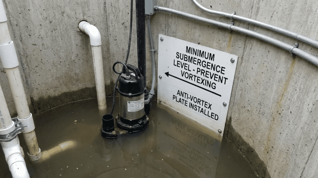
Does adding a “vortex breaker” or “umbrella” on the pump fix bad design?
An anti-vortex plate (umbrella) mounted on the pump suction bell is a useful accessory that increases the effective submergence by forcing the flow path to lengthen. However, it is not a cure-all. It can suppress surface vortices but cannot correct large-scale bulk rotation or severe velocity unevenness caused by poor civil design. It should be used as a safety factor, not a substitute for proper dimensions.
What is the typical cost of ignoring HI 9.8 standards?
Ignoring HI 9.8 standards often results in pumps that require overhaul every 2-3 years instead of every 10-15 years. The lifecycle cost implications include repeated seal and bearing replacements ($5K-$20K per event), energy penalties from air entrainment (5-10% efficiency loss), and the potential for catastrophic station flooding if pumps air-bind during peak events.
Conclusion
Key Takeaways
- Physics over Hardware: The best pump cannot overcome the physics of a poor wet well. The civil design dictates mechanical reliability.
- Calculate, Don’t Guess: Use the ANSI/HI 9.8 formula S = D(1 + 2.3 Fd) to determine minimum submergence. Do not rely on “rule of thumb” elevations.
- Respect Dimensions: Floor clearance (C) and back wall clearance (B) are as critical as submergence. Violating these creates subsurface vortices.
- Control Integration: Ensure SCADA level setpoints respect the calculated hydraulic minimums, not just the physical pump height.
- Prevent Rotation: Pre-swirl is a silent killer of bearings. Use baffles, fillets, and splitters to enforce uniform flow.
The successful application of Non-Clog Wastewater Pumps Wet Well Design and Minimum Submergence to Prevent Vortexing requires a shift in perspective. The wet well is not merely a holding tank; it is a complex hydraulic structure that conditions the fluid for the machinery. For municipal engineers and operators, the goal is to achieve a stable hydraulic environment that allows the pump to operate within its design envelope.
By adhering to Hydraulic Institute standards, carefully calculating submergence requirements based on specific speed and Froude numbers, and recognizing the maintenance implications of civil geometry, engineers can design systems that last decades rather than years. When in doubt, invest in the upfront analysis—whether through detailed calculations or CFD modeling—as the cost of correction after concrete is poured is exponentially higher. The reliability of the entire wastewater network often relies on the invisible fluid dynamics occurring beneath the grating.