
Selection Guide: How to Specify Metering Pumps for Municipal Lift Stations
Introduction
Municipal engineers frequently underestimate the complexity of chemical injection at remote lift stations. While the primary sewage pumps receive the bulk of the design attention, the auxiliary chemical feed systems are often the critical defense against the wastewater industry’s most pervasive enemies: hydrogen sulfide ($H_2S$) corrosion, noxious odors, and Fat, Oil, and Grease (FOG) accumulation. A poorly specified metering pump in a remote lift station leads to vapor-locked lines, untreated sewage entering the force main, and accelerated degradation of concrete infrastructure—potentially costing utilities millions in premature rehabilitation costs.
Within the broader metering pumps category, lift station service represents the most demanding duty class an engineer is likely to specify. The pump is unattended for days at a time, exposed to ambient temperature swings of 60°F or more, fed from a tote that may sit half-empty for weeks, and expected to inject against a force main whose pressure changes every time a sewage pump starts. Every specification decision made in this section — technology, materials, controls, accessories — must be evaluated against that unsupervised operating reality rather than against a laboratory bench-test curve.
This article serves as a comprehensive Selection Guide: How to Specify Metering Pumps for Municipal Lift Stations. Unlike treatment plant applications where operators are present daily, lift station equipment must operate autonomously in harsh, uncontrolled environments. The chemical feed systems here are typically tasked with dosing Calcium Nitrate, Sodium Hypochlorite, Ferric salts, or proprietary biological additives into the wet well or force main. These applications demand a distinct set of engineering criteria compared to standard process dosing.
The consequences of poor selection include frequent site visits for re-priming, loss of chemical containment, and failure to meet environmental compliance regarding odor control. This guide will help engineers, directors, and operators navigate the specific hydraulic, material, and control challenges inherent to lift station chemical metering, ensuring long-term reliability and accurate dosage control.
Metering Pump Operations: Subcategory Overview
Specification is only the first stage of a metering pump’s service life. Once the unit is installed at a lift station, two operational disciplines determine whether the specification actually delivers the intended dose: reading and applying the pump curve correctly, and matching wetted materials to the chemical over the full temperature and concentration range. Both topics are covered in dedicated guides below, and both should be reviewed before a specification package is issued for bid — decisions made on paper are far cheaper to change than a pump head that has already been installed and grouted into a chemical skid.
Pump Curve Reading for Metering Pump Operators
Metering pumps are frequently treated as if their output were purely a function of stroke setting, but every positive-displacement metering pump has a capacity-versus-backpressure relationship that shifts as check valves wear, as viscosity changes with temperature, and as discharge pressure rises. Practical metering pump curve reading teaches operators to interpret rated capacity, slip, and the effective control band rather than trusting the digital percentage display. The single most useful concept for lift station staff is the accurate control band: most metering pumps hold their stated volumetric accuracy (typically ±1% to ±3% of setpoint) only between roughly 30% and 90% of rated capacity, and accuracy degrades sharply below about 10%.
At a lift station, this matters because the diurnal flow curve can swing the required feed rate by a factor of five or more between the 7:00 a.m. peak and the 3:00 a.m. trough. If the pump was sized for peak flow with no consideration of the low end, it will be operating deep in the inaccurate portion of its curve for a third of every day. Understanding where the curve becomes unreliable is what drives the decision between one large pump with a 1000:1 digital turndown and two smaller duty-staged pumps. Curve literacy also underpins draw-down calibration: an operator who knows the expected slip at a given backpressure can tell the difference between a fouled check valve and a normal pressure-related capacity shift.
Materials Selection for Metering Pump Wetted Ends
The second operational discipline is metallurgical and polymer compatibility. Detailed materials selection for metering pumps — comparing cast iron, 316 stainless, and duplex alloys alongside the engineered polymers used in dosing service — determines whether a pump head survives five years or five months in a given chemical. For lift station chemical feed the polymer side of the decision usually dominates, because the aggressive oxidizers and acid salts used for odor control attack metals that perform perfectly well in raw sewage service.
Sodium hypochlorite is the clearest example: 316 stainless steel, which is the default wetted material for countless wastewater applications, suffers rapid pitting and chloride stress-corrosion cracking in 12.5% hypo, while PVC, PVDF, and PTFE perform reliably. Ferric chloride is similarly unforgiving of stainless and requires PVDF or lined heads with ceramic or PTFE ball checks to resist both corrosion and abrasion. Elastomer selection deserves equal scrutiny — EPDM, Viton, Hypalon, and PTFE-faced diaphragms each have a different compatibility profile, and a diaphragm that swells or hardens will change displaced volume long before it actually ruptures. Where the chemical is a proprietary blend, the specification should require the supplier to confirm compatibility in writing at the maximum expected ambient temperature rather than relying on a generic chart.
How to Select / Specify
Developing a robust specification requires analyzing the intersection of chemical properties, hydraulic constraints, and the unique operating rhythm of a sewage lift station. This section outlines the critical criteria for the Selection Guide: How to Specify Metering Pumps for Municipal Lift Stations.
Duty Conditions & Operating Envelope
The operating envelope for a lift station metering pump is defined by the diurnal flow curve of the wastewater collection system. Unlike constant-process applications, lift station flows can vary largely from peak morning usage to near-zero flow in the middle of the night.
- Turndown Ratio: Because wastewater flow is highly variable, the metering pump must possess a high turndown ratio (typically 100:1 or greater) to accurately dose chemicals during low-flow periods without losing prime. A pump that cannot turn down sufficiently will overdose chemicals at night, wasting operational budget.
- Intermittent vs. Continuous: Engineers must determine if the chemical feed should be continuous (dosing the wet well to prevent septicity) or intermittent (locked to the run-status of the main sewage pumps for force main injection).
- Pressure Transients: If injecting directly into a force main, the metering pump must overcome the line pressure. However, it must also be robust enough to withstand pressure spikes (water hammer) caused by the start/stop cycles of the main sewage pumps, necessitating robust check valves or isolation strategies.
Materials & Compatibility
The chemical selected dictates the material construction of the pump’s “wet end.” Mismatching materials is a leading cause of early failure.
- Sodium Hypochlorite: Requires venting capabilities due to off-gassing. Wetted parts should be PVC, PVDF, or specialized elastomers. Avoid stainless steel in direct contact.
- Calcium Nitrate / Bioxide: generally compatible with standard materials but can crystallize if allowed to stagnate.
- Ferric Chloride: Highly corrosive and abrasive. Requires robust plastic head construction (PVDF/PTFE) and abrasive-resistant check valves.
- FOG/Biological Additives: Often viscous. Tubing or diaphragm materials must be selected to prevent swelling or degradation from organic solvents sometimes present in proprietary blends.
Hydraulics & Process Performance
Lift station applications often involve suction lift scenarios, where the chemical storage (tote or tank) is at grade level, and the pump may be mounted on top of the tank or a nearby skid.
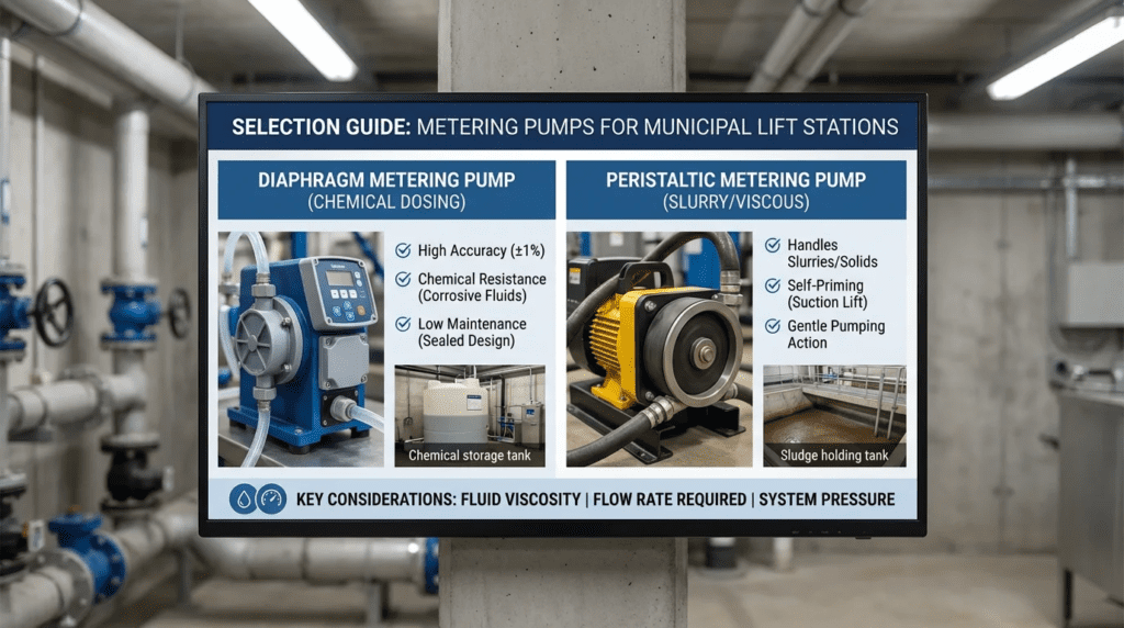
- Suction Lift: If the pump is located above the chemical tank, it must be self-priming. Peristaltic pumps are superior here, capable of pulling 25+ feet of suction lift, whereas diaphragm pumps may struggle if the prime is lost.
- Viscosity Handling: In cold weather, the viscosity of certain chemicals increases. The specification must account for the fluid’s behavior at the lowest expected ambient temperature.
- Off-Gassing Fluids: Fluids like hypochlorite release gas bubbles when pressure drops or temperature rises. In standard diaphragm pumps, this gas can accumulate in the head, causing “vapor lock” where the diaphragm moves but pumps nothing. High-velocity flushing or peristaltic designs are required to mitigate this.
Installation Environment & Constructability
Lift stations are frequently located in residential neighborhoods, roadside easements, or low-lying areas. Space is at a premium.
- Space Constraints: Retrofit projects often require fitting chemical feed systems into existing valve vaults or small control buildings. Skid-mounted systems with a small footprint are preferred.
- Outdoor Ratings: If not housed in a building, the pump and controller must be NEMA 4X (IP66) rated to withstand rain, snow, and direct sun. UV resistance is critical for plastic enclosures.
- Security: Chemical tanks and pumps at unmanned stations are vulnerability points. Enclosures must be lockable and tamper-resistant to prevent vandalism or accidental exposure to the public.
Reliability, Redundancy & Failure Modes
In a plant, an operator walks by daily. At a lift station, a pump may not be inspected for a week. Reliability is the primary driver of lifecycle cost.
- Run-Dry Capability: It is common for chemical totes to run empty before an operator arrives. Pumps that fail immediately upon running dry (e.g., certain mag-drive or cavity pumps) are poor choices. Peristaltic pumps can typically run dry indefinitely without damage.
- Leak Detection: Specifications should require integral leak detection systems that shut down the pump and send a SCADA alarm if a diaphragm ruptures or a tube bursts.
- Redundancy: For critical odor control sites (e.g., near high-value real estate), a duty/standby (N+1) configuration is recommended. Automatic switchover upon fault ensures continuous treatment.
Controls & Automation Interfaces
The metering pump must integrate seamlessly with the lift station’s RTU or PLC.
- Pacing Methods:
- Flow Proportional: 4-20mA signal from the station’s magnetic flow meter.
- Pump Run Status: Digital input triggers dosing only when main pumps are active.
- Timer Based: Simple programmed diurnal curve (less accurate but cheaper).
- SCADA Integration: Critical feedback points for the specification include “Pump Running,” “General Fault,” “Leak Detected,” and “Chemical Low Level.”
Maintainability, Safety & Access
Maintenance at lift stations is often performed by a single operator working out of a truck.
- Tool-Less Maintenance: Preference should be given to pumps that allow tube or diaphragm changes without special tools.
- Chemical Containment: Double-walled containment for tanks and tubing (dual-containment hose) is often required by environmental regulations to prevent spills into the environment.
- Ergonomics: Pumps should be mounted at waist height. If mounted on top of tall tanks, permanent access platforms or ladders must be specified to prevent unsafe climbing.
Lifecycle Cost Drivers
Engineers must evaluate the Total Cost of Ownership (TCO), not just the bid price.
- Consumables: Analyze the cost and frequency of replacement parts. For peristaltic pumps, the tube is the only wear part. For diaphragm pumps, check valves, seals, and diaphragms constitute the kit.
- Chemical Costs: An accurate pump saves money. A pump that overdoses by 10% due to poor turndown control can cost a utility tens of thousands of dollars in wasted chemical annually.
- Service Calls: The highest cost driver is the “truck roll.” Selecting a cheaper pump that requires weekly de-gassing or calibration is significantly more expensive than a robust pump that runs for months untouched.
Comparison Tables
The following tables provide a direct comparison of the technologies and application scenarios relevant to the Selection Guide: How to Specify Metering Pumps for Municipal Lift Stations. Use Table 1 to select the pump technology and Table 2 to determine the application fit.
| Technology | Primary Features | Best-Fit Applications | Limitations | Maintenance Profile |
|---|---|---|---|---|
| Peristaltic (Hose/Tube) | – Self-priming (high suction lift) – Can run dry – No check valves to clog – Handles off-gassing fluids perfectly |
– Sodium Hypochlorite – Viscous polymers – High-suction lift scenarios – Remote/unmanned sites |
– Limited discharge pressure (typically <125 psi) – Periodic tube replacement required |
Low/Predictable: Change tube/hose every 3-12 months. No other wetted parts to service. |
| Solenoid Diaphragm | – Low initial cost – High precision at fixed conditions – Compact footprint |
– Clean, simple chemicals – Indoor/climate-controlled stations – Flooded suction applications |
– Prone to vapor lock (off-gassing) – Check valves foul with dirty fluids – Poor suction lift capabilities |
Moderate: Requires regular cleaning of check valves. Diaphragm replacement 12-24 months. |
| Motor-Driven Diaphragm | – Higher pressure capabilities – Robust mechanical drive – Higher flow rates |
– Injection into high-pressure force mains – Large volume dosing (Master Lift Stations) |
– Higher CAPEX – Susceptible to vapor lock without auto-degassing heads – Check valve maintenance |
Moderate: Oil changes for gearbox, diaphragm kits, check valve cleaning. |
| Progressive Cavity | – Non-pulsating flow – Handles high solids/sludge |
– Polymer activation (rare in lift stations) – Extremely viscous fluids |
– Cannot run dry (instant stator failure) – Expensive repair parts – Large footprint |
High: Stator and rotor wear. Seal maintenance. strictly requires run-dry protection. |
| Application Scenario | Chemical Agent | Key Constraint | Recommended Pump Type | Critical Spec Feature |
|---|---|---|---|---|
| Odor Control (H2S) | Calcium Nitrate / Bioxide | Variable flow pacing required | Peristaltic or Motor Diaphragm | 4-20mA input for flow pacing; High turndown ratio. |
| Disinfection / Septicity | Sodium Hypochlorite (Bleach) | Gas binding (Vapor lock) | Peristaltic | Must handle gas bubbles without loss of prime. |
| FOG Control | Bacteria / Enzymes | Low flow rates; Viscous fluid | Peristaltic | Timer-based batch dosing; wide tube ID for viscosity. |
| Force Main Injection | Ferric Chloride / Iron Salts | High backpressure; Corrosive | Motor Diaphragm (Hydraulic or Mechanical) | PVDF/Teflon wetted parts; Injection quill with check valve. |
Selection & Specification Framework
The comparison tables narrow the field, but they do not resolve the trade-offs that arise when two technologies both appear acceptable. The framework below walks through the decision in the order the constraints actually bind: chemical first, then hydraulics, then control strategy, then site logistics. Working the sequence in that order prevents the most common specification failure, which is choosing a pump technology on price and then discovering that the chemical or the suction condition rules it out.
Step 1 — Let the Chemical Eliminate Technologies
Start by listing the chemical, its concentration, its specific gravity, and its off-gassing behavior at the maximum expected ambient temperature. Sodium hypochlorite at 12.5% will off-gas aggressively above roughly 85°F, which eliminates conventional solenoid diaphragm heads unless auto-degassing is provided. Ferric chloride eliminates any head containing stainless steel or standard elastomers. Viscous FOG-control blends above about 500 cP eliminate small solenoid pumps regardless of head material, because the suction stroke cannot fill the chamber in the available time. Where the site doses more than one chemical, the framework is applied separately to each feed system — a single “standard” pump model rarely suits both an oxidizer and a nitrate salt.
Step 2 — Resolve the Suction Condition
Determine whether the pump sees flooded suction or suction lift, and quantify the lift in feet from the lowest liquid level in the tote to the pump centerline. Flooded suction opens the field to nearly any technology. A suction lift greater than about 5 feet begins to disqualify solenoid diaphragm units in off-gassing service; above 10 feet, peristaltic designs become the practical default. Note that the governing case is the tote at its low-level alarm point, not at delivery level — a system that primes beautifully against a full tote can lose prime every time the tote reaches 15% remaining.
Step 3 — Choose the Pacing Strategy Before the Pump Size
Flow-proportional pacing from a magnetic flow meter gives the tightest dose control but demands a pump with a genuine high-turndown drive. Pump-run-status pacing is simpler and works well for force main injection where dosing only needs to occur while the sewage pumps are moving liquid. Timer-based dosing is acceptable for FOG control and small stations where the diurnal curve is stable and the chemical is inexpensive. The pacing choice determines the required turndown, and the required turndown determines whether one pump or a duty-staged pair is needed. This is the point where diaphragm metering pump designs and hose pumps genuinely diverge: modern stepper-driven diaphragm units can achieve 1000:1 turndown with excellent linearity, whereas hose pumps are typically limited by minimum stable motor speed and are better paced by on/off batching at very low duties.
Step 4 — Confirm the Chemical Family Against Dedicated Guidance
Odor and septicity control at collection-system lift stations overlaps heavily with plant-side dosing practice, and the specification for oxidizers, coagulants, and pH adjustment chemicals draws on the same body of knowledge. Engineers writing a lift station package should cross-check their chemical assumptions against the broader guidance on chemical metering pumps, particularly for solution strength, degradation rate in storage, and the accessory package (backpressure valve, pressure relief, calibration column) that each chemical family requires. Where a lift station feeds a chemical that will ultimately reach a treatment plant’s process stream, coordinating the two specifications avoids conflicting material standards across the same utility.
Worked Example — Sizing Against Turndown, Not Just Peak
Consider a station with a peak hour flow of 1.8 MGD, an average daily flow of 0.55 MGD, and a minimum night flow of 0.15 MGD. Calcium nitrate is dosed volumetrically at 3.0 gallons per 10,000 gallons of wastewater.
- Peak demand: 1,800,000 GPD × 0.0003 = 540 GPD ÷ 24 = 22.5 GPH
- Average demand: 550,000 GPD × 0.0003 = 165 GPD ÷ 24 = 6.9 GPH
- Minimum night demand: 150,000 GPD × 0.0003 = 45 GPD ÷ 24 = 1.9 GPH
- Required operating span: 22.5 ÷ 1.9 = 11.8:1
A pump rated for 25 GPH would run at 90% at peak and 7.6% at night — below the accurate control band for most designs. Selecting a 30 GPH pump moves the peak point to 75% and the night point to 6.3%, which is worse at the low end, not better. The correct response is either a pump with a certified 100:1 or greater turndown and demonstrated linearity below 10%, or a two-pump arrangement in which a 25 GPH unit handles daytime flow-paced duty and a 5 GPH unit handles the overnight trough. The second option costs more in CAPEX and panel space but keeps both pumps inside their accurate range at all times, and it delivers redundancy for the odor-control mission at no additional pump cost.
Step 5 — Weigh Lifecycle Cost Against Truck Rolls
Finalize the choice on total cost of ownership using a five-year horizon. Build the comparison from four line items: purchase and installation, consumables (tubes, diaphragms, check valve cartridges), chemical waste attributable to dosing inaccuracy, and labor for scheduled plus unscheduled site visits. At most utilities the labor line dominates. If a fully burdened truck roll costs $250 to $450 and a marginal technology choice adds one unscheduled visit per month, that decision carries a five-year penalty of $15,000 to $27,000 — a figure that routinely exceeds the entire purchase price difference between competing pumps.
Engineer & Operator Field Notes
Beyond the catalog specifications, real-world success relies on proper implementation. The following notes are derived from field experience in commissioning and maintaining lift station chemical feeds.
Commissioning & Acceptance Testing
Commissioning a metering pump at a lift station requires verifying performance across the full flow range, not just a “bump test.”
- Draw-Down Calibration: Every installation must include a calibration column (draw-down cylinder) on the suction side. The SAT (Site Acceptance Test) must involve running the pump at 50% and 100% speed and measuring the physical volume drawn from the column over 60 seconds. Relying on the digital display alone is insufficient.
- Backpressure Verification: Simulate the worst-case force main pressure during testing to ensure the pump can inject against the main sewage pumps when they are running.
- Restoration of Auto: A common failure point is the “Auto-Reset.” Simulate a power outage. When power is restored, the pump should automatically return to its previous “Auto” state without requiring an operator to physically press “Start.”
Common Specification Mistakes
Engineers often copy-paste specifications from treatment plant projects to lift stations, leading to errors.
- Oversizing: Specifying a pump where the normal operating point is the bottom 5% of its range results in “slug dosing” rather than smooth injection. Metering pumps are most accurate between 30% and 90% of their rated capacity.
- Ignoring Suction Piping: Using soft, clear vinyl tubing on the suction side of a high-lift application can lead to the tubing collapsing under vacuum. Always specify rigid piping or reinforced braided hose for suction lines.
- Missing Injection Quills: Injecting chemical directly into a pipe wall causes corrosion at the tap. A retractable injection quill allows the chemical to be dispersed into the center of the flow stream, protecting the pipe and ensuring better mixing.
Troubleshooting by Symptom
Most lift station chemical feed complaints resolve to one of four symptom patterns, and each has a short diagnostic path an operator can run from the truck.
- Pump runs, no chemical delivered: Almost always vapor lock (off-gassing chemical) or a lost prime on a suction-lift installation. Check the suction line for a gas pocket at the high point before touching the pump head. On diaphragm units, verify the degassing valve is open and not crystallized shut.
- Dose drifts low over weeks: Progressive check valve fouling or diaphragm fatigue. Confirm with a draw-down test at fixed speed and compare against the commissioning baseline — a 10% to 20% shortfall at the same setpoint is the signature.
- Erratic output, audible knocking: Cavitation on the suction stroke from an undersized or collapsed suction line, or excessive suction lift as the tote empties. Measure actual lift at low-level alarm rather than at the current liquid level.
- Repeated leak alarms: Chemical attack on the diaphragm or tube material. Treat this as a materials selection problem rather than a maintenance problem — replacing the same incompatible part on a shorter cycle only reduces the interval between spills.
O&M Burden & Strategy
Operational strategies must align with the “remote” nature of the site.
- Tube/Diaphragm Life: For peristaltic pumps, the hose is a sacrificial part. The maintenance schedule should be based on hours run. If a pump runs 24/7, the tube may need changing quarterly. If it runs intermittently, it may last a year.
- Check Valve Hygiene: For diaphragm pumps, ball checks are the Achilles’ heel. Grit, crystallization, or trash can unseat the ball. Operators should keep spare check valve assemblies (cartridges) in the truck for quick swaps rather than trying to clean them on-site.
- Predictive Maintenance: Modern smart pumps can output “Tube Failure” or “Diaphragm Rupture” alarms. These should be mapped to the central SCADA system as high-priority alarms to prevent environmental spills.
Design Details / Calculations
Proper sizing is the foundation of the Selection Guide: How to Specify Metering Pumps for Municipal Lift Stations. The following methodology ensures the pump meets process requirements.
Sizing Logic & Methodology
To size the pump, you must calculate the required chemical feed rate in Gallons Per Hour (GPH).
Step 1: Determine the Chemical Mass Required
$$Mass (lbs/day) = Flow (MGD) times Dosage (mg/L) times 8.34$$
Note: Flow should be the Peak Hourly Flow for sizing the max capacity, and Average Daily Flow for operational estimates.
Step 2: Convert Mass to Gallons of Solution
Most chemicals are not 100% active. You must account for solution strength and specific gravity.
$$Volume (GPD) = frac{Mass (lbs/day)}{Specific Gravity times 8.34 times (% Solution/100)}$$
Step 3: Convert to Pump Output (GPH)
$$Rate (GPH) = frac{Volume (GPD)}{24 hours}$$
Design Example:
A lift station has a peak flow of 2.0 MGD. We need to dose Bioxide (Calcium Nitrate) at 3.5 gallons per 10,000 gallons of flow (a common volume-based metric for Bioxide).
- Peak Flow = 2,000,000 GPD
- Dosage Rate = 3.5 gal / 10,000 gal = 0.00035 ratio
- Required Pump Capacity = 2,000,000 * 0.00035 = 700 GPD
- 700 GPD / 24 hr = 29.17 GPH
Selection: Select a pump capable of ~40-50 GPH to ensure the operating point (29 GPH) is in the middle of the curve, allowing room for future flow increases.
Specification Checklist
When writing the Division 43 or 46 specification, ensure these items are explicitly called out:
- Turndown Ratio: Minimum 100:1 (for digital stepper motor driven pumps) or 1000:1 for high-end units.
- Wetted Materials: Explicitly state compatibility (e.g., “All wetted parts shall be compatible with 12.5% Sodium Hypochlorite”).
- Motor Enclosure: TEFC or TENV, with NEMA 4X controller housing.
- Control Inputs: 4-20mA analog input, Remote Start/Stop dry contact.
- Safety Accessories: Backpressure valve, pressure relief valve, calibration column, and pulsation dampener (if diaphragm type).
- Leak Detection: Integral float or conductivity sensor in the pump head or housing.
- Accuracy Statement: Steady-state volumetric accuracy of ±1% or better across the stated turndown range, verified by draw-down test at 25%, 50%, and 100% of rated capacity during the Site Acceptance Test.
- Containment: Dual-containment discharge tubing from the pump skid to the injection point, with the annulus terminated inside the containment area and monitored where required by state rule.
- Spare Parts: One complete wetted-end repair kit per pump furnished at substantial completion, plus a documented parts list with manufacturer part numbers for the operations group.
Standards & Compliance
Lift station chemical feed installations are governed by a layered set of standards rather than a single controlling document. At minimum, a complete specification should reference NSF/ANSI 61 for wetted materials where the chemical can reach a potable or reuse stream, ANSI/AWWA standards for the chemical being fed (including B300 for hypochlorite and B301 for liquid chlorine handling practice where applicable), NFPA 70 (NEC) Article 500 for area classification at wet well and vault locations, and the applicable OSHA 29 CFR 1910 provisions for machine guarding and hazard communication. State regulations frequently add secondary containment and spill reporting requirements beyond these baselines.
- NSF/ANSI 61: If the lift station discharges upstream of a water reuse facility or if the chemical enters a potable source (rare for lift stations, but applicable to source water pumping), wetted parts must be NSF 61 certified.
- OSHA 1910: Safety guards on all rotating couplings. Chemical labeling requirements.
- NEC (NFPA 70): Electrical wiring methods, particularly if the lift station wet well is classified as a hazardous location (Class 1 Div 1 or 2). Note: Chemical pumps are usually in a safe zone, but if located inside the wet well vault, explosion-proof motors may be required.
Frequently Asked Questions
Why are peristaltic pumps often preferred over diaphragm pumps for lift stations?
Peristaltic (hose) pumps are often preferred in the Selection Guide: How to Specify Metering Pumps for Municipal Lift Stations because they are self-priming, can run dry without damage, and do not have check valves. Lift station applications often involve off-gassing chemicals (like hypochlorite) and suction lift conditions that cause diaphragm pumps to vapor lock or lose prime. The lower maintenance requirement of simply changing a hose is ideal for remote, unmanned sites.
How do I determine the correct backpressure rating for the metering pump?
The metering pump must be rated for a pressure higher than the maximum possible pressure in the receiving pipe. For force main injection, this is the force main dynamic head plus friction losses, plus a safety margin (typically 10-15%). However, you must also account for pressure spikes (water hammer) caused by the main sewage pumps starting and stopping. Installing an injection quill with an integral check valve helps isolate the metering pump from these spikes.
What is the difference between “Manual Pacing” and “Flow Pacing”?
Manual pacing involves setting the pump to run at a fixed speed (e.g., 50%) whenever it is on. This is simple but inefficient for lift stations with variable flow. Flow pacing (or flow proportional dosing) utilizes a 4-20mA signal from the lift station’s flow meter to automatically adjust the chemical pump speed to match the incoming wastewater flow. This maintains a constant chemical dosage (ppm) regardless of flow volume, preventing waste and ensuring compliance.
How often should metering pump tubing be replaced?
For peristaltic pumps in continuous lift station service, tubing typically requires replacement every 3 to 6 months, or up to 12 months for intermittent duty. Factors affecting tube life include the chemical being pumped, the system pressure, the pump speed (rpm), and ambient temperature. Most manufacturers provide life-expectancy charts based on hours of operation. It is best practice to replace tubes proactively during scheduled preventive maintenance rather than waiting for failure.
Can I install the chemical pump inside the wet well?
Generally, no. Installing chemical metering pumps inside the wet well is discouraged due to corrosion, difficult access for maintenance, and electrical classification issues (Class 1 Division 1 environments). Best practice is to locate the chemical pump and tank in a separate, ventilated enclosure or building at grade level, and run the discharge tubing down into the wet well or force main valve vault.
Should a lift station use one large metering pump or two smaller ones?
The answer depends on the required operating span between peak and minimum flow. If peak demand divided by minimum night demand exceeds roughly 10:1, a single pump will spend part of every day below its accurate control band unless it carries a certified 100:1 or better turndown with demonstrated linearity at the low end. Two duty-staged pumps — a larger unit for flow-paced daytime service and a smaller unit for the overnight trough — keep both machines inside their accurate range and provide partial redundancy for odor control at little additional cost. For stations where the diurnal swing is modest or the chemical is inexpensive, a single high-turndown pump with a standby unit on the shelf is usually the simpler and cheaper answer.
Conclusion
Key Takeaways for Specifying Lift Station Metering Pumps
- Prioritize Reliability: Choose pumps that can handle suction lift and run-dry conditions (e.g., peristaltic) for remote, unmanned sites.
- Check Chemical Compatibility: Ensure wetted materials (elastomers, heads, fittings) match the specific chemical (Hypo, Bioxide, Ferric) to prevent catastrophic leaks.
- Automate Dosing: Use flow pacing (4-20mA) or pump-run-status interlocks to match chemical feed to the highly variable diurnal flow curve.
- Manage Off-Gassing: For Sodium Hypochlorite, avoid standard diaphragm pumps unless equipped with auto-degassing heads; peristaltic is generally safer.
- Include Accessories: Never specify a pump without a calibration column, backpressure valve, and proper injection quill.
- Total Cost of Ownership: Factor in the labor cost of “truck rolls” to remote sites—a slightly more expensive, reliable pump pays for itself by preventing one emergency call-out.
- Size for Turndown, Not Peak: Calculate the ratio of peak to minimum night demand first; if it exceeds about 10:1, either specify certified high-turndown linearity or stage two pumps so neither operates below its accurate control band.
Specifying the correct equipment using this Selection Guide: How to Specify Metering Pumps for Municipal Lift Stations is critical for the longevity of wastewater infrastructure. While the metering pump is a small fraction of the station’s total cost, its failure leads to septic conditions, odor complaints, and rapid corrosion of concrete assets.
Engineers must move beyond simple catalog flow rates and consider the holistic environment of the lift station: the intermittent flows, the remote location, the harsh weather, and the specific chemical properties. By selecting robust technologies like peristaltic pumps for difficult fluids, integrating smart control strategies, and designing for maintainability, utilities can ensure their chemical feed systems protect their infrastructure effectively for decades.