
Aeration System Sizing & Design: Peak Load and Turndown Guide
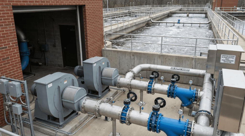
Introduction to Biological Oxygen Demands
One of the most persistent engineering challenges in wastewater treatment plant (WWTP) design is the “aeration paradox.” Biological processes require aeration systems capable of meeting the ultimate 20-year peak hourly organic load, but these same systems must operate efficiently under the severely reduced organic and hydraulic loads present during the plant’s early life or low-flow nighttime periods. Failing to properly address this duality in an Aeration System Sizing & Design: Peak Load and Turndown Guide leads to systems that suffer from catastrophic surge conditions, excessive energy consumption, and poor biological nutrient removal due to over-aeration.
Sizing is the decision that locks in everything else. Within the broader landscape of wastewater aeration systems, the blower and diffuser selections made during design determine the plant’s energy profile, maintenance burden, and process flexibility for two decades. Controls optimize within the envelope sizing establishes; they cannot widen it. A blower package that physically cannot turn down below 1,500 scfm will vent air on quiet nights regardless of how sophisticated the algorithm above it is.
Aeration typically accounts for 50% to 60% of a municipal or industrial wastewater treatment facility’s total energy expenditure. Oversizing blowers solely for maximum duty—without engineering a precise turndown strategy—results in wasted capital expenditure (CAPEX) and exorbitant operational expenditure (OPEX). Furthermore, excess air entering anoxic or anaerobic zones via internal mixed liquor recycle can destroy biological phosphorus and nitrogen removal processes.
Proper aeration system engineering spans a wide landscape of sub-disciplines, including biological modeling, blower thermodynamics, diffuser oxygen transfer kinetics, and advanced control algorithms. This comprehensive engineering guide explores the full spectrum of technologies, process strategies, and sizing methodologies required to achieve both absolute peak load performance and precise, energy-efficient turndown.
Subcategory Landscape — Types, Technologies & Approaches
Successfully navigating aeration design requires understanding that an aeration system is not a single piece of equipment, but a highly interactive network. The sizing and turndown capabilities are dictated by four primary pillars: the compression technology (blowers), the mass transfer interface (diffusers/aerators), the automated control strategy, and the biological load modeling approach. Engineers must carefully match components across these categories to ensure the system’s surge limits, turndown ratios, and dynamic wet pressures align with process demands.
Blower & Compression Technologies
Positive Displacement (PD) Lobe Blowers are the traditional workhorses of the municipal wastewater industry, utilizing two rotating, interlocking lobes to trap and push a constant volume of air against system backpressure. They are most typically used in small-to-medium plants, aerobic digesters, and channel aeration applications where pressures fluctuate but flow demands remain relatively consistent. The primary advantage of PD lobe blowers is their exceptional turndown capability; when paired with a VFD, they can often turn down to 25-30% of their design flow without the risk of aerodynamic surge. However, they are inherently less efficient than centrifugal designs at higher pressures (above 7-8 psig) and generate significant noise and pulsation. For engineers, the critical specification factor is managing the slip-to-speed ratio, as volumetric efficiency degrades heavily at very low VFD frequencies.
Hybrid Rotary Screw Blowers bridge the gap between traditional lobe blowers and high-speed turbos by utilizing interlocking helical rotors that compress air internally before it exits the discharge port. Used heavily in medium-sized municipal plants and industrial facilities operating in the 10-15 psig range, they offer 20-30% better wire-to-air efficiency than lobe blowers. Because they are positive displacement machines, screw blowers bypass the aerodynamic surge limitations of centrifugal blowers, allowing for a highly robust turndown ratio—often achieving 75-80% turndown. The main limitation is their higher initial capital cost compared to lobe blowers and stricter oil/bearing maintenance requirements. Specifying engineers must ensure the internal compression ratio of the selected machine closely matches the actual system backpressure to prevent over-compression and wasted energy.
Multistage Centrifugal Blowers utilize a series of rotating impellers separated by stationary baffles to gradually build pressure through dynamic compression. They are a staple in mid-to-large capacity plants with relatively steady base-load requirements. Their primary advantage lies in their ruggedness, longevity (often lasting 20-30+ years), and low-frequency noise profile. Control and turndown are traditionally managed via an inlet butterfly valve rather than a VFD, which reduces power consumption by throttling intake air, though they typically max out at a 50-60% turndown before hitting surge conditions. Engineers must carefully plot the system resistance curve against the blower’s variable pressure-volume curve to ensure the unit does not drop off its performance map during low-flow periods.
Single-Stage Centrifugal Blowers feature a single, internally geared high-speed impeller and rely on sophisticated mechanical components—Inlet Guide Vanes (IGVs) and Variable Diffuser Vanes (VDVs)—to control flow and pressure. These are standard in large-scale (50+ MGD) municipal facilities that require massive airflows. The dual-vane control allows these machines to efficiently adjust to varying atmospheric conditions and system backpressures, achieving excellent wire-to-air efficiency at peak loads. However, they are highly mechanically complex, requiring specialized maintenance, and typically only achieve a 45-50% turndown before aerodynamic surge occurs. Specifications must include strict vibration monitoring and precise mapping of the IGV/VDV linkage algorithms.
Gearless High-Speed Turbo Blowers represent the modern standard for energy efficiency, utilizing direct-drive permanent magnet motors spinning on either air foil or active magnetic bearings at 20,000 to 40,000 RPM. They are widely applied in activated sludge plants seeking maximum energy optimization and carbon footprint reduction. The major advantage is their exceptionally high wire-to-air efficiency and minimal maintenance requirements, as there is no mechanical gearing or oil to change. The critical limitation is their strict aerodynamic surge line, which tightly restricts turndown—often limiting them to only 45-55% turndown capability. Engineers must specify a highly responsive surge-protection control loop and often pair them with smaller “trim” blowers to handle deep nocturnal low-flow periods.
Blower selection is also constrained by which manufacturers support a given technology at a given scale and location. Reviewing the field of OEMs supplying aeration equipment early reveals where genuine competition exists and where a technology choice narrows the bid list to one or two suppliers. High-speed turbos carry a narrower service footprint than legacy centrifugal machines, and a plant far from the nearest factory-trained technician should weigh that against the efficiency gain.
Aeration & Mass Transfer Equipment
Fine Bubble Diffusers, available in disc, tube, or panel configurations, produce micro-bubbles (1-3 mm) to maximize the gas-liquid interfacial surface area, providing the highest Standard Oxygen Transfer Efficiency (SOTE) of any aeration type (typically 1.5-2.5% per foot of submergence). They are universally applied in standard municipal activated sludge basins. While they minimize blower air volume requirements at peak loads, they suffer from higher dynamic wet pressure (DWP) drop and are highly susceptible to biological and inorganic fouling, which steadily increases system backpressure over time. Engineers sizing blowers for fine bubble systems must include a fouling allowance (typically 0.5 to 1.5 psi) in the system curve to ensure the blower can overcome aged diffuser resistance at peak load.
Coarse Bubble Diffusers release large air bubbles (5-10 mm) that provide aggressive mixing and turbulent shear, though at a significantly lower SOTE (typically 0.7-1.0% per foot). They are applied in aerobic digesters, channel aeration, post-aeration tanks, and heavy industrial wastewater where high solids or scaling potentials would quickly clog fine pores. The primary advantage is their virtually maintenance-free operation and low headloss. While they require larger blower capacities to meet peak oxygen demands, their “alpha factor” (the ratio of dirty water transfer to clean water transfer) remains much higher and more stable than fine bubble systems in thick mixed liquor scenarios.
Jet Aeration Systems combine motive liquid pumping with injected air, forcing a high-velocity two-phase plume into the wastewater. They are specifically suited for very deep tanks (25+ feet), industrial applications, SBRs, and oxidation ditches where independent control of mixing and aeration is required. A major process advantage is their superior turndown capability during anoxic periods; the blower can be turned off entirely while the motive liquid pump continues to provide necessary biological suspension. However, they require dual mechanical systems (pumps and blowers), increasing overall complexity. Sizing calculations must account for the specific gravity of the pumped fluid and the frictional losses through the jet manifold.
Mechanical Surface Aerators float on or are rigidly mounted to the surface of the basin, using impellers or rotors to violently agitate the surface, throwing liquid into the air to entrain oxygen. They are ubiquitous in aerated lagoons, oxidation ditches, and rural treatment plants where simplified O&M is prioritized over energy efficiency. Unlike diffused systems, they do not rely on blowers, eliminating the complexities of pneumatic backpressure and aerodynamic surge. Their major limitation is extremely poor turndown control; they are usually operated in basic on/off cycles or via VFDs within a very narrow speed range (typically only 15-20% turndown) before they lose the ability to maintain adequate bottom-mixing velocity.
The full spectrum of mass transfer options extends beyond the four covered here. Broader guidance on the different types of water aeration techniques covers cascade and gravity aeration, spray and tray systems, and packed towers used in drinking water for iron and manganese oxidation and gas stripping — different process objectives, sized against mass transfer of a target contaminant rather than biological demand.
Process Controls & Optimization Strategies
Dissolved Oxygen (DO) Control Systems form the baseline automation strategy for modern plants, using submerged optical or galvanic probes to monitor residual oxygen and cascading PID loops to adjust blower speeds and aeration control valves. By maintaining a strict DO setpoint (typically 1.5-2.0 mg/L), these systems prevent over-aeration during diurnal low flows. The main limitation is that DO is a lagging indicator; by the time DO drops, the biological oxygen demand has already spiked. To optimize turndown, engineers must ensure the DO control algorithms are properly tuned to prevent “hunting,” where blowers repeatedly ramp up and down, pushing centrifugal units precariously close to their surge lines.
Ammonia-Based Aeration Control (ABAC) represents the next generation of process optimization, integrating real-time ammonia (NH4+) and nitrate (NO3-) sensors into the aeration control loop. Instead of maintaining a static DO setpoint, ABAC allows the DO setpoint to float based on the actual influent nitrogen load. During low-load periods, ABAC can drop the DO setpoint to 0.5 mg/L, unlocking massive turndown potential and saving 10-20% more energy than standard DO control. However, ABAC requires highly skilled operators, frequent sensor calibration, and blowers capable of extremely deep turndown to realize the benefits without venting air.
Most Open Valve (MOV) Control Strategy is a pressure-optimization algorithm used in systems with multiple aeration zones and automated basin valves. It continuously monitors the position of all aeration valves and adjusts the main blower pressure setpoint downward until at least one valve is nearly 100% open (typically 85-95%). Implementing MOV prevents the blowers from over-pressurizing the header and forcing valves to throttle unnecessarily, thereby reducing total dynamic head and saving power. Specifying engineers must ensure valve actuators have rapid, continuous duty cycles and high-resolution position feedback to make this strategy viable.
Variable Frequency Drive (VFD) Turndown Optimization involves manipulating the electrical frequency supplied to the blower motor to vary its rotational speed in direct response to process demand. It is the primary method for achieving turndown in PD, Screw, and Turbo blowers. Proper VFD optimization requires careful matching of the blower’s affinity laws to the system curve. Engineers must be acutely aware that while flow reduces proportionally with speed, the minimum speed is often dictated by the static head of the water column; slowing a centrifugal blower too much will cause the system pressure to exceed the blower’s discharge pressure, resulting in immediate and damaging aerodynamic surge.
Biological Loading & Sizing Scenarios
Peak Hourly Organic Load Sizing focuses on calculating the maximum possible biological and nitrogenous oxygen demand expected during the plant’s design life (often a projected 20-year future state). It accounts for first-flush rain events, industrial dumps, and diurnal population spikes. While sizing for peak hourly load is mandatory for regulatory compliance, doing so in isolation results in massively oversized blowers. Engineers must calculate the ratio between this absolute peak and the current average day load. If the ratio exceeds 3:1, a multi-blower “split sizing” approach (e.g., mixing a large turbo blower for peak with a smaller screw blower for base) is required to prevent control failure.
Diurnal Load Variation Management addresses the massive swings in oxygen demand that occur within a single 24-hour cycle. In municipal plants, flow and organic load peak between 8:00 AM–10:00 AM and again around 7:00 PM, while plunging to a fraction of the average between 2:00 AM–5:00 AM. This requires the aeration system to seamlessly hand off operation between multiple blowers without pressure drops or DO spikes. Successful management dictates overlapping blower performance maps, ensuring the maximum turndown of two running blowers is lower than the maximum output of a single running blower, preventing control “dead bands.”
Seasonal Temperature Sizing (AOR to SOR) reconciles the competing thermodynamic and biological effects of water temperature. In summer, wastewater is warm: biological kinetic rates peak (demanding high oxygen), but the physical saturation point of oxygen in water plummets, requiring maximum air volume. In winter, biological rates slow and oxygen dissolves easily, requiring minimum air volume. Seasonal sizing ensures that the blowers can provide the massive summer volumetric flows without over-aerating during the winter. Summer conditions almost always dictate the system’s maximum scfm, while winter conditions dictate the deepest required turndown limits.
Deep Dives: Peak Load Sizing and Turndown
The two halves of the sizing problem pull in opposite directions. Peak load determines how large the equipment must be; turndown determines how small it must be able to become.
Sizing Aeration for Peak Load
Detailed guidance on how to size aeration for peak load works through the calculation chain from influent characterization to installed blower capacity, including the coincidence question that trips up most designs. Peak values for flow, BOD, ammonia, and temperature rarely occur simultaneously, and stacking every worst case into one design point compounds conservatism until the result is a blower package the plant will never approach.
Peak hour flow and maximum month organic load are driven by different mechanisms — one hydraulic and short, one loading-driven and sustained. A defensible approach evaluates several credible load combinations and sizes against the governing one rather than multiplying independent peaks. The reward is not merely a cheaper blower; it is a blower whose minimum turndown is proportionally lower, which makes the entire low-flow problem easier.
Achieving and Verifying Aeration Turndown
Coverage of aeration turndown addresses the constraint that most often goes unspecified and unverified. Turndown is quoted three different ways — as a percentage of design flow, as a ratio, or as a minimum stable scfm — and comparing bids across those conventions without normalizing them produces meaningless comparisons.
Two verification points matter more than the headline number. Turndown must be stated at actual system pressure, not the manufacturer’s test point: a centrifugal blower’s surge line moves with backpressure, so a machine quoted at 50% turndown at 6 psig may manage far less at the 8.5 psig an aged diffuser grid presents. And the specification should require demonstrated combined turndown for the full package including trim blowers, tested at commissioning against real basin conditions.
Selection & Specification Framework
Choosing the correct combination of technologies for aeration system sizing requires a rigorous decision framework that balances Capital Expenditure (CAPEX) with Operational Expenditure (OPEX), while prioritizing the crucial “Turndown Gap.”
The Turndown Gap Analysis
The most critical error an engineer can make is selecting a blower technology solely based on peak efficiency. For example, if a plant requires 6,000 scfm at peak 20-year summer loads, an engineer might select two 3,000 scfm Gearless High-Speed Turbo Blowers. However, if the current, Year-1 nocturnal low-flow requirement is only 900 scfm, the system will fail. A 3,000 scfm turbo blower typically has a 50% turndown, meaning its minimum flow is 1,500 scfm. Pushing 1,500 scfm into a process that only needs 900 scfm strips out alkalinity, destroys the anoxic zone via DO carryover, and wastes energy. In this scenario, integrating a 1,000 scfm Hybrid Rotary Screw Blower to act as the deep-turndown trim blower alongside the high-efficiency turbos is the correct framework.
CAPEX vs. OPEX Tradeoffs
Plant size dictates the economic viability of certain technologies. For small plants (<1 MGD), the OPEX savings of high-speed turbos or advanced Ammonia-Based Aeration Control (ABAC) will rarely pay back the steep initial CAPEX and integration costs within a 15-year lifecycle. In these applications, VFD-driven Positive Displacement (PD) Lobe Blowers paired with robust Coarse Bubble Diffusers or standard Fine Bubble Diffusers provide reliable, easy-to-maintain functionality. Conversely, for plants >5 MGD, upgrading from lobe to turbo blowers and implementing Most Open Valve (MOV) Control Strategy can yield hundreds of thousands of dollars in annual energy savings, achieving payback in under three years.
Specification Pitfalls
A common specification pitfall is failing to properly communicate system backpressure variations to the blower manufacturer. Diffuser fouling increases static pressure, while varying basin levels (e.g., in SBRs) drastically shift the system curve. If a centrifugal blower is specified for a static pressure of 7.5 psig, but aged Fine Bubble Diffusers and a high basin level push the pressure to 8.5 psig, the blower’s operating point will shift left into the surge region, forcing it to either trip offline or vent air, completely destroying the plant’s turndown capability.
Worked Example — Peak scfm and the Turndown Floor
A 6 MGD plant must oxidize 11,500 lb/day BOD and 2,300 lb/day ammonia at peak summer conditions. At 1.1 lb O₂/lb BOD and 4.6 lb O₂/lb NH₃-N, AOR = 12,650 + 10,580 = 23,230 lb O₂/day, or 968 lb/hr.
- AOR to SOR: with alpha 0.55, beta 0.95, a 15-foot fine bubble grid, and 2.0 mg/L operating DO at 25°C, the correction factor works out near 0.48. SOR = 968 ÷ 0.48 = 2,017 lb O₂/hr
- Air required: at 24% SOTE (1.6% per foot × 15 ft) and 0.0175 lb O₂ per standard cubic foot of air: 2,017 ÷ (0.0175 × 0.24) = 4,802 scfm at peak
- Mixing floor: two basins totaling 12,000 ft² at 0.12 scfm/ft² = 1,440 scfm minimum
- Year-1 night demand: roughly 22% of design peak ≈ 1,060 scfm — below the mixing floor
The governing minimum is 1,440 scfm, set by mixing rather than oxygen demand — a distinction that changes the blower selection entirely. The span is 4,802 down to 1,440, a ratio of 3.3:1. Two 2,400 scfm turbos at 50% turndown reach 1,200 scfm on one machine, clearing the floor. But check the handoff: two at minimum deliver 2,400 scfm and one maxes at 2,400 scfm, so the transition is exactly continuous with no margin, and any degradation opens a control dead band.
A more robust arrangement is one 3,000 scfm turbo plus an 1,800 scfm screw blower turning down to 450 scfm: the screw covers 450 to 1,800, the turbo 1,500 to 3,000, both together 4,800 — real overlap at every transition. Check the mixing floor before assuming oxygen demand sets the minimum, and verify handoff overlap rather than trusting that the arithmetic sums.
Comparison Tables
The following tables provide a quick-reference engineering matrix for comparing the mechanical profiles and application suitability of the various aeration subcategories.
Table 1: Aeration & Compression Technology Subcategory Comparison
| Type / Technology | Key Features | Typical Turndown Limit | Relative Efficiency / SOTE | Maintenance Profile |
|---|---|---|---|---|
| Positive Displacement (PD) Lobe Blowers | Constant volume, VFD control, highly resistant to pressure fluctuations. | 25% – 30% of design flow | Low/Moderate (Drops heavily at >8 psig) | High: Oil changes, belt tensioning, vibration checks. |
| Hybrid Rotary Screw Blowers | Internal compression, VFD control, wider operating maps than PD. | 20% – 25% of design flow | Moderate/High | Moderate: Oil changes, specialized block rebuilding. |
| Multistage Centrifugal Blowers | Dynamic compression, robust cast-iron housings, inlet throttling. | 50% – 60% of design flow | Moderate | Low: Bearing grease, long lifecycle, highly durable. |
| Single-Stage Centrifugal Blowers | Geared, controlled via inlet guide vanes and variable diffuser vanes. | 45% – 50% of design flow | High | High: Complex gearboxes, oil systems, vane calibration. |
| Gearless High-Speed Turbo Blowers | Direct drive, air/magnetic bearings, highly integrated VFD/PLC. | 45% – 55% of design flow | Very High | Low: Filter changes only, zero oil, specialized OEM repair. |
| Fine Bubble Diffusers | Micro-bubble generation, highest surface area per cfm. | Limited by mixing constraints (typ. 0.12 scfm/ft² min) | Very High (1.5-2.5% per ft) | High: Susceptible to biological fouling and scaling, requires acid/gas cleaning. |
| Coarse Bubble Diffusers | Large bubbles, high turbulence, non-clog designs. | Very high turndown without losing mixing capability. | Low (0.7-1.0% per ft) | Very Low: Highly resistant to clogging, long lifecycle. |
Table 2: Process & Application Fit Matrix
| Application / Operating Condition | Optimal Strategy / Equipment Focus | Key Engineering Constraint |
|---|---|---|
| High diurnal swing with extreme nocturnal lows | Split blower sizing (Turbo + Screw), Variable Frequency Drive (VFD) Turndown Optimization | Must ensure overlapping blower surge lines to prevent control dead-bands. |
| Advanced BNR process with strict Total Nitrogen limits | Ammonia-Based Aeration Control (ABAC), Fine Bubble Diffusers | Requires high operator skill level and frequent probe calibration. |
| Large multi-basin plant >10 MGD | Most Open Valve (MOV) Control Strategy, Single-Stage Centrifugal Blowers | Valve actuators must handle continuous fine-tuning without burning out. |
| Heavy industrial / high-strength solids | Jet Aeration Systems or Coarse Bubble Diffusers | Mass transfer alpha factor drops significantly in thick MLSS; requires careful modeling. |
| Extreme summer vs winter temperature gaps | Seasonal Temperature Sizing (AOR to SOR) | Winter minimum scfm requirements often dictate the selection of a smaller, dedicated trim blower. |
Engineer & Operator Field Notes
Aeration systems only perform as well as they are maintained and operated. Practical, field-level realities span across all subcategories of equipment and control strategies.
Commissioning Considerations
Commissioning an aeration system requires different approaches depending on the technology. When commissioning Gearless High-Speed Turbo Blowers, engineers must perform a “surge test” in the field to plot the exact surge line against real-world static water head. This is drastically different from commissioning Positive Displacement (PD) Lobe Blowers, where the primary focus is verifying proper belt tension, checking oil levels, and ensuring the relief valve is correctly set. For Fine Bubble Diffusers, a clean water oxygen transfer test (ASCE/EWRI 2-06) is often required to verify SOTE before mixed liquor is introduced, whereas Mechanical Surface Aerators primarily require motor amp draw validation at varying submergence depths.
A catastrophic error during commissioning is failing to adequately blow out the stainless steel air headers before installing Fine Bubble Diffusers. Construction debris (welding slag, PVC shavings, dirt) trapped in the header will be blown directly into the bottom of the diffuser membranes, causing irreversible localized blinding and tearing upon startup. Always commission blowers using temporary blow-off valves before the diffusers are installed.
Common Specification Mistakes
Engineers frequently confuse the control methodologies between dynamic and positive displacement machines. A common mistake is attempting to use a discharge throttling valve to control the flow of Hybrid Rotary Screw Blowers. Because they are positive displacement, throttling the discharge only increases system pressure and power draw until the motor overloads or the relief valve pops. Throttling is strictly reserved for Multistage Centrifugal Blowers (via inlet valves) or regulating header pressure in large multi-basin grids.
Another error relates to Seasonal Temperature Sizing (AOR to SOR). Engineers sometimes input “average” ambient air temperatures into blower sizing software. Blower capacity must be specified at the worst-case site conditions (highest ambient summer temperature, highest relative humidity, lowest barometric pressure) because hot, humid air is less dense, significantly reducing the mass flow of oxygen delivered per cubic foot of air.
O&M Comparison Across Subcategories
The daily operational burden shifts radically depending on the chosen technology:
- Operator Attention: Ammonia-Based Aeration Control (ABAC) requires the highest level of daily attention, demanding operators clean and calibrate ion-selective electrodes (ISE) weekly. Conversely, traditional Dissolved Oxygen (DO) Control Systems using optical probes only require a quick wipe-down bi-weekly.
- Maintenance Intervals: Single-Stage Centrifugal Blowers demand strict, specialized maintenance (oil analysis, vibration monitoring, IGV linkage greasing). In contrast, Gearless High-Speed Turbo Blowers are incredibly hands-off, usually requiring only a simple air filter change every 6-12 months.
- Consumables: Systems utilizing Fine Bubble Diffusers must budget for membrane replacement every 5-8 years depending on the sludge age and industrial load, as well as regular liquid acid (e.g., formic or acetic acid) dosing systems to clean scaling without draining the tanks. Coarse Bubble Diffusers require almost zero consumables over a 20-year lifespan.
- Skill Levels: Tuning Most Open Valve (MOV) Control Strategy PID loops requires advanced SCADA programming skills, while operating VFD-driven lobe blowers in manual mode requires only basic operator knowledge.
Troubleshooting Overview
When an aeration system fails to meet demand or trips offline, the root cause is usually linked to specific subcategory traits:
- Symptom: Blower surging (loud popping/chuffing sounds, heavy vibration).
- Root Cause (Centrifugal/Turbo): The system backpressure exceeds the blower’s capability at its current speed. Often caused by aged Fine Bubble Diffusers increasing static head, or the Variable Frequency Drive (VFD) Turndown Optimization logic slowing the blower down too much during diurnal low flows.
- Symptom: High localized DO in one basin, zero DO in another.
- Root Cause (Process Control): Poorly tuned Most Open Valve (MOV) Control Strategy causing the valves to hunt, or uneven diffuser fouling across the grid leading to airflow short-circuiting to the cleanest diffusers.
- Symptom: Blower motor overloading despite low airflow.
- Root Cause (PD/Screw): Blocked air filter, closed discharge isolation valve, or failure of Hybrid Rotary Screw Blowers internal bearings causing rotor drag.
When implementing deep turndown strategies to manage Diurnal Load Variation Management, engineers often focus only on biological oxygen demand. However, activated sludge requires a minimum amount of air (typically 0.12 scfm/ft² of floor area) simply to keep the mixed liquor suspended. Turning blowers down past this floor to save energy will cause solids to settle, creating anaerobic dead zones and septic sludge.
Design Details & Standards
Aeration design requires rigorous mathematical modeling to translate biological requirements into mechanical equipment specifications.
Sizing Methodology: AOR to SOR Conversion
The core of aeration sizing is converting the Actual Oxygen Requirement (AOR)—the pounds of oxygen the bacteria need per day to oxidize BOD and ammonia under specific site conditions—into the Standard Oxygen Requirement (SOR). SOR normalizes the requirement to clean water at sea level at 20°C, which is how manufacturers rate their diffusers and blowers.
The conversion is governed by the equation:
SOR = AOR / [ α × ( (β × τ × Ω × Csat − DO) / 9.09 ) × 1.024(T−20) ]
Engineers must carefully establish the Alpha factor (α), which represents the ratio of oxygen transfer in wastewater versus clean water. Peak Hourly Organic Load Sizing calculations must account for the fact that alpha is lower at the front of an aeration basin (where surfactants and raw organics are high) and recovers toward the back of the basin.
Key Design Parameters by Subcategory
How an engineer approaches sizing fundamentally changes based on the equipment:
- Diffuser Type: If specifying Coarse Bubble Diffusers, the Alpha factor might be estimated at a stable 0.70 to 0.85. If specifying Fine Bubble Diffusers, Alpha might plummet to 0.40 in the primary aerobic zone, drastically increasing the required SOR and scfm.
- Elevation & Temperature: Gearless High-Speed Turbo Blowers and Multistage Centrifugal Blowers are highly sensitive to air density. An aeration system at 5,000 feet elevation on a 100°F day requires a physically larger centrifugal blower to push the same mass of oxygen as one at sea level. Positive Displacement (PD) Lobe Blowers are less sensitive to density changes but will run hotter at altitude.
Applicable Standards & Compliance
Aeration specifications assemble requirements from performance test codes, transfer-efficiency standards, and facility design criteria. Packaged blower performance is verified under ASME PTC 13 on a wire-to-air basis, custom machines under ASME PTC 10. Oxygen transfer is measured under ASCE/EWRI 2-06 in clean water and ASCE 18-96 in process water. Facility criteria follow the Ten States Standards (GLUMRB) or state equivalents, with process practice from WEF MOP 8 and MOP 32. Motor efficiency follows NEMA MG 1 and 10 CFR Part 431; drives and panels follow NFPA 70 and UL 508A. Enclosed blower rooms invoke OSHA 29 CFR 1910.95 for noise — a requirement lobe blower installations frequently fail without acoustic enclosures.
Specification checklists should always reference the following industry standards:
- ASME PTC 13 (Wire-to-Air Performance Test Code): The modern standard for evaluating packaged high-speed compressors (like Turbos and Screws). It ensures manufacturers guarantee the total power consumed by the entire package (motor, VFD, cooling fans, filters), not just the bare shaft horsepower.
- ASME PTC 10: The older standard, still heavily used for testing the aerodynamic performance of custom-engineered Multistage Centrifugal Blowers and Single-Stage Centrifugal Blowers.
- ASCE/EWRI 2-06 & 18-96: The definitive standards for testing the oxygen transfer efficiency of diffusers in clean and dirty water, essential for verifying performance during commissioning.
- WEF Manual of Practice (MOP) 8: Design of Municipal Wastewater Treatment Plants. The ultimate guidebook outlining accepted ranges for mixing requirements, scfm/ft² limits, and Diurnal Load Variation Management protocols.
Specification Checklist
A robust specification for aeration systems should mandate:
- Clear definitions of AOR, SOR, and required scfm at Minimum, Average, and Peak loads.
- Site conditions: Maximum and minimum ambient temperature, relative humidity, and site elevation.
- Water depths: Minimum and maximum operating liquid levels, plus diffuser submergence depth.
- Fouling allowances: A stated pressure allowance (e.g., +1.0 psi) to account for aging diffusers over 10 years.
- Turndown guarantee: A strict requirement that the combined blower package can meet the minimum flow without bypassing air to the atmosphere.
- Turndown stated at actual design backpressure including the fouling allowance, normalized to a common convention across all bidders.
- The controlling minimum flow identified as either mixing-limited or demand-limited, with the calculation shown.
- Demonstrated combined package turndown verified at commissioning under real basin conditions, not calculated by summing machine ratings.
FAQ Section
What are the different types of aeration blowers and diffusers?
Aeration systems rely on specific combinations of equipment. Blower technologies include Positive Displacement (PD) Lobe Blowers for rugged, low-pressure applications, Hybrid Rotary Screw Blowers for medium efficiency and wide turndown, Multistage Centrifugal Blowers for baseline durability, Single-Stage Centrifugal Blowers for massive volume generation, and Gearless High-Speed Turbo Blowers for maximum energy efficiency. Mass transfer is achieved via Fine Bubble Diffusers for high efficiency, Coarse Bubble Diffusers for heavy mixing, Jet Aeration Systems for deep tanks, or Mechanical Surface Aerators for lagoon applications.
How do you choose between Gearless High-Speed Turbo Blowers and Hybrid Rotary Screw Blowers?
The choice heavily depends on the required turndown ratio and lifecycle CAPEX/OPEX. Turbo blowers offer the highest wire-to-air efficiency at design points but are limited by aerodynamic surge, often restricting turndown to 45-50%. They are ideal for base-loading. Screw blowers are positive displacement machines, immune to aerodynamic surge, allowing them to turn down to 20-30%. Engineers frequently use a hybrid design: large turbos for Peak Hourly Organic Load Sizing and a smaller screw blower for nocturnal low flows.
What is the most cost-effective aeration control strategy for small plants?
For small plants (<1 MGD), complex algorithms like Ammonia-Based Aeration Control (ABAC) are rarely cost-effective due to high instrument maintenance. The best approach is combining a robust Dissolved Oxygen (DO) Control System with basic Variable Frequency Drive (VFD) Turndown Optimization on the blowers. This ensures the plant matches energy input to basic biological demand without overwhelming operators with calibration requirements.
How does seasonal temperature affect aeration system sizing?
Seasonal Temperature Sizing (AOR to SOR) is critical because temperature drives two opposing forces. In hot summer months, biological demand is highest, but oxygen solubility in water is at its lowest, meaning the blowers must deliver maximum scfm. In winter, solubility is high, meaning fewer scfm are needed. Therefore, summer dictates the physical maximum size of the blower, while winter dictates the absolute minimum turndown requirement.
Why do fine bubble diffusers increase energy consumption over time?
Fine Bubble Diffusers rely on micro-pores in EPDM, silicone, or polyurethane membranes. Over time, these pores suffer from biological fouling (slime) and inorganic scaling (calcium/iron deposits). This restricts airflow, increasing the Dynamic Wet Pressure (DWP). The blowers must then work harder, drawing more electrical amperage to push the same volume of air through the fouled pores. Routine acid cleaning and pressure monitoring are required to mitigate this.
Should blowers be sized for the 20-year projection or for current load?
Size the building, electrical service, header, and foundations for the 20-year projection; size the installed machines for 8 to 12 years, with designated space and connections for a future unit. Blowers installed today will likely be replaced before the design horizon arrives, and a machine sized for a load two decades out spends its early life fighting its own turndown limit — precisely the condition that causes surging, air venting, and DO excursions into anoxic zones. What is genuinely expensive to add later is the concrete, conduit, and transformer capacity; the blower itself is straightforward to add when the load materializes.
Conclusion
Key Takeaways: Aeration Sizing & Turndown
- Design for the Turndown Gap: Do not just calculate Peak Hourly Organic Load Sizing. Ensure the selected blower configuration can efficiently reach the nocturnal low-flow demand without surging or venting air.
- Mix Blower Technologies: Consider split sizing. Base-load with Gearless High-Speed Turbo Blowers for efficiency, but use Hybrid Rotary Screw Blowers to handle deep turndown periods seamlessly.
- Account for Diffuser Aging: Always add a pressure fouling allowance (typ. 1.0 psi) when pairing blowers with Fine Bubble Diffusers to ensure long-term performance.
- Optimize Controls Systematically: Upgrade from static setpoints to Most Open Valve (MOV) Control Strategy to minimize header pressure, and consider Ammonia-Based Aeration Control (ABAC) if strict nitrogen limits exist.
- Remember Mixing Limits: No matter how deep your Variable Frequency Drive (VFD) Turndown Optimization goes, you must maintain at least 0.12 scfm/ft² in an activated sludge basin to keep solids in suspension.
- Find the Governing Minimum First: Mixing frequently sets the floor rather than oxygen demand. Calculate both and state which controls.
- Verify Handoff Overlap: Two machines at minimum must deliver less than one at maximum, with margin. Arithmetic that sums exactly leaves a dead band the first time either degrades.
Mastering aeration system sizing requires an integrated engineering methodology. The true cost of an aeration system is realized not on the day the purchase order is signed, but over the 20-year operational lifecycle where energy and maintenance dictate the total cost of ownership. By carefully evaluating the complete array of compression technologies, mass transfer interfaces, and automation strategies, engineers can design facilities that are robust enough to handle the inevitable peaks, yet nimble enough to conserve energy during deep low-flow periods. Engaging with specialized process modelers and blower manufacturers early in the design phase, and adhering to strict ASME and WEF standards, ensures a plant that balances process stability, biological health, and municipal budget constraints.