
Butterfly Valves Sizing and Selection: Cv
Introduction
One of the most frequent and costly errors in municipal water and wastewater engineering is sizing a control valve to match the adjacent pipe diameter without performing hydraulic calculations. This line-sizing approach produces valves that operate nearly closed, which leads to control hunting, premature seat wear, and cavitation damage. Avoiding it requires understanding the flow coefficient, Cv, which is the first step in specifying a valve that provides stable control, minimizes head loss, and delivers a reliable service life.
Butterfly valves are ubiquitous in municipal plants, industrial wastewater facilities, and distribution systems — used for isolation and modulating control on raw water intakes, aeration air headers, pump station discharge, and chemical feed. Their compact face-to-face dimension, high flow capacity, and cost make them the default for large-diameter piping, and the wider case for and against them is set out in the discussion of butterfly valves as a valve class.
The deceptive simplicity of the type leads to improper specification. Wrong seat material, misunderstood torque, or miscalculated Cv for modulating service produces snapped shafts, shredded elastomeric seats, water hammer, and early replacement. This article provides a technical framework for specification, sizing, and lifecycle management.
How to Select and Specify
Duty Conditions & Operating Envelope
Define the operating envelope first: minimum, normal, and maximum flow rates with corresponding upstream and downstream pressures at each. Typical design velocities in municipal water piping fall in the range of 3 to 8 ft/s for sustained service. AWWA C504 permits rubber-seated butterfly valves to be applied up to 16 ft/s, but that is a maximum rating for the valve, not a design target for the pipeline — sustained operation near it produces high hydrodynamic torque and vibration, and it should not be confused with normal design practice.
Distinguish isolation from modulating duty. An isolation valve requires little analysis of partial-open hydraulics; a modulating valve depends entirely on accurate flow coefficient data across its stroke. Account for future capacity honestly: a valve sized for 20-year peak flow may sit at 10% open for its first five years, which places it squarely in the cavitation zone. Where that is the case, smaller parallel valves or a reduced-trim option is the correct answer.
Materials & Compatibility
Ductile iron (ASTM A536) bodies are standard for water and wastewater service. Discs are typically 316 stainless steel, aluminum bronze, or epoxy-coated ductile iron. Highly corrosive industrial wastewater or desalination duty may require duplex stainless or higher alloys.
Seat and seal materials need rigorous compatibility checks. EPDM is standard for potable water and aeration air to approximately 250 °F (120 °C), and it degrades rapidly in the presence of hydrocarbons. Where the wastewater carries fats, oils, and greases or petroleum derivatives, nitrile (Buna-N) is the correct specification. For aggressive chemical dosing, PTFE-lined valves are required, at the cost of higher operating torque.
Understanding Cv
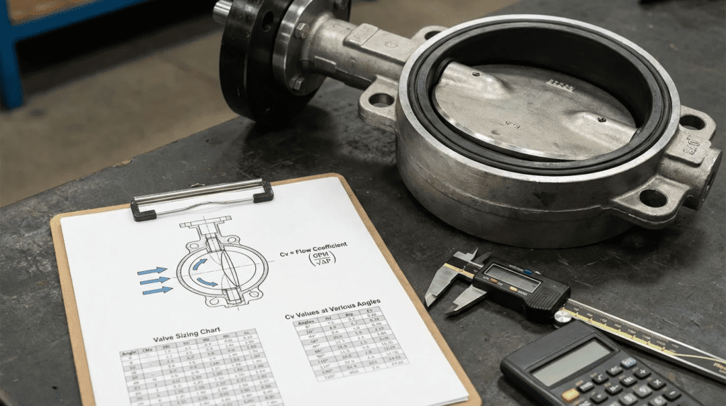
The flow coefficient, Cv, is the volume of water in US gallons per minute at 60 °F that flows through a valve at a pressure drop of 1 psi. In butterfly valves the inherent characteristic is non-linear, approximating equal-percentage behaviour through the mid-stroke before flattening as the disc approaches full open.
For isolation valves the goal is a high full-open Cv to minimize parasitic head loss and pumping energy. For modulating valves the objective is entirely different: a properly sized control butterfly valve should operate between roughly 30% and 70% open at normal flow. Sizing so that normal flow requires 15% opening concentrates the entire pressure drop across a narrow annular gap, generating high-velocity jets that cause cavitation, noise, and rapid seat erosion.
Installation Environment & Constructability
Three body styles are common. Wafer valves are sandwiched between pipe flanges and rely on the flange bolts for structural integrity; they cannot be used for dead-end service. Lug valves have threaded inserts, permitting removal of downstream piping while the valve holds pressure, though the dead-end pressure rating is usually reduced. Flanged valves to AWWA C504 are standard for large-diameter municipal service because of their structural rigidity and resistance to pipeline stress.
Account for disc clearance. The disc swings into the adjacent piping, and if the valve is installed too close to a pump discharge, check valve, reducer, or a thick-walled cement-lined section, the disc will strike it and the valve will never open fully.
Reliability, Redundancy & Failure Modes
The most common mechanical failure in elastomer-seated butterfly valves is seat tearing or extrusion from high-velocity flow at low opening angles. The second is shaft shearing, which is almost always a torque calculation failure.
Torque has three components: seating and unseating torque from friction between disc and seat, bearing friction torque from the shaft rotating under pressure load, and hydrodynamic torque from the fluid acting on the disc. Hydrodynamic torque peaks in the region of 70° to 80° open. If the actuator is not sized to overcome that peak, the valve stalls or the shaft shears.
Controls & Automation Interfaces
Specify the actuator type and the control interface together. When integrating with SCADA, define the communication protocol and the required feedback: position feedback, open and close limit switches, and fault alarms. For modulating service a smart positioner comparing the control signal to actual shaft position is essential, and the better ones track total strokes and breakaway torque trends, which supports predictive maintenance.
Maintainability, Safety & Access
Actuators fifteen feet in the air without platform access will be neglected. Specify chain-wheel operators for manual valves out of reach, or remote displays for automated ones. Manual gear operators must accept a padlock in the closed position for lockout. And closing a large butterfly valve too quickly induces water hammer — actuator stroke times must be calculated from the transient analysis of the pipeline, commonly landing in the range of 60 to 120 seconds for large transmission mains.
Lifecycle Cost Drivers
The primary lifecycle cost driver is pumping energy. A valve with restrictive internal geometry and low full-open Cv creates permanent head loss, and over a 20-year life the electrical cost of pumping against that loss can exceed the capital cost of the valve by a wide margin. Other drivers are the labor for seat replacement and inventory for spare actuators and positioners.
PRO TIP: Actuator Torque Safety Factors
Never size an actuator on clean-water seating torque alone. Apply a safety factor — typically 1.25 to 1.5 — to account for seat swelling, long periods of inactivity raising breakaway torque, and mineral scaling on the disc edge. In wastewater and sludge service, 1.5 to 2.0 is appropriate.
Cv Is a Curve, Not a Number
The single most common misuse of Cv in specifications is treating it as a property of the valve. It is not. Cv is a property of the valve at a given disc angle, and the number a manufacturer publishes in a catalog table is almost always the full-open value.
That matters because a modulating valve never operates at full open. The Cv that governs its behaviour is the value at 40%, or 50%, or 60% travel — and the relationship between those values is steeply non-linear. Across the mid-stroke, a few degrees of disc rotation can change capacity by a substantial fraction, which is precisely why an oversized butterfly valve hunts: the controller is asking for a small correction and the valve delivers a large one.
Three practical consequences follow. First, require the full Cv-versus-opening table in the submittal, not the headline figure, and do the sizing arithmetic against it. A selection made from a single number cannot be checked. Second, size using the flow range, not the design point: calculate the required Cv at minimum, normal, and maximum flow, then confirm all three fall within the controllable band of the same valve. A valve that is ideal at normal flow and pinned near closed at minimum flow will spend the night hunting. Third, where the required turndown cannot be accommodated by one valve, use two in parallel — a small valve for normal flow and a larger one staged in for peaks — rather than accepting poor control across the range.
One further point on characterization: because the inherent curve is non-linear, a controller tuned for a linear response will be unstable at one end of the stroke and sluggish at the other. Either specify signal characterization in the controller to linearize the response, or accept that the loop must be tuned conservatively enough to be stable at the most sensitive part of the travel.
Comparison Tables
| Technology | Design Features | Best-Fit Applications | Limitations | Maintenance Profile |
|---|---|---|---|---|
| Concentric (rubber seated) | Stem centered in the disc; disc in constant contact with the seat through the full stroke. | Standard water and wastewater, aeration air, low-pressure slurries (AWWA C504). | Constant friction drives seat wear. Limited to lower pressures and temperatures. | High. Seats require periodic replacement from frictional wear and elastomer aging. |
| Double offset (high performance) | Stem offset from the disc centerline and the pipe centerline; camming action lifts the disc off the seat. | Higher-pressure water, industrial wastewater, chemical service. | Higher capital cost. Preferred sealing direction; bi-directional service usually de-rated. | Medium. Reduced seat friction extends life significantly over concentric designs. |
| Triple offset (metal seated) | Three offsets with a conical sealing profile; effectively no seat friction until final closure. | Extreme temperatures, severe scaling service, strict shutoff requirements. | Highest capital cost. Sensitive to pipeline debris scratching the metal sealing surface. | Low in normal service. Seat damage from debris is complex and costly to repair. |
| Application | Recommended Type | Key Constraints & Sizing Focus | Relative Cost |
|---|---|---|---|
| Pump discharge isolation | Concentric flanged (AWWA C504) | Maximize full-open Cv to reduce head loss. Actuator must handle hydrodynamic torque during pump start and stop. | $ |
| Aeration air modulating control | High-performance double offset | Cv sizing for compressible flow. Elevated discharge temperature. Requires signal characterization for stable control. | $$ |
| Primary sludge isolation | Concentric with nitrile seat | Elastomer compatibility with FOG. Torque safety factor of at least 1.5 for solids buildup. | $ |
| High-pressure membrane feed | Double offset, duplex stainless | Chloride corrosion resistance. High differential pressure. Cavitation check mandatory. | $$$ |
Engineer & Operator Field Notes
Commissioning & Acceptance Testing
For critical or large-diameter valves, require certified hydrostatic shell testing and seat leakage testing in accordance with AWWA C504 or the applicable industrial standard, with the test pressures stated in the specification rather than left to the manufacturer.
During site acceptance, verify stroke time and limit switch settings. A common finding is that the automated valve travels slightly past 90 degrees or stops short, leaving the seat unloaded and the valve leaking. Stroke fully open and closed several times, confirming that position feedback corresponds exactly to the mechanical indicator.
Common Specification Mistakes
The most pervasive error is line-sizing a modulating valve. If a 16-inch line requires flow control, the default is a 16-inch valve — but the hydraulic calculation frequently shows that a 10-inch or 12-inch valve delivers the correct Cv to control within the 30% to 70% band. The line-sized valve modulates at 10% to 15% open, stripping the seat and vibrating.
The second is specifying wafer-style valves where downstream piping may be removed for maintenance. Wafer valves rely on compression from both adjacent flanges; removing one flange releases the valve. Specify lug or flanged bodies where end-of-line or one-sided service is anticipated.
The third is requesting only the full-open Cv in the submittal, which makes the sizing uncheckable.
O&M Burden & Strategy
Resilient-seated valves require active management. An isolation valve left in one position for five years will suffer seat bonding and mineral scaling, and breakaway torque will exceed actuator capacity exactly when emergency operation is needed. Enforce an exercising program — partial close and reopen at a defined interval — and stock replacement seat rings, packing kits, and at least one spare actuator and positioner for critical modulating service.
Troubleshooting Guide
- Continuous leakage when fully closed. Limit switch calibration stopping travel before full seat engagement, debris trapped between disc and seat, or abrasive wear of the elastomer. Recalibrate first; replace the seat only if that does not resolve it.
- Actuator hunting. The valve is oversized for the required Cv, so small angular changes produce large flow changes. Tune the deadband as an interim measure; resolve permanently by characterizing the signal, reducing trim, or reselecting the valve.
- Popping or crackling noise. Cavitation — static pressure falling below vapor pressure across the valve, forming bubbles that collapse violently. Limit the differential, keep the valve above roughly 30% open, or introduce backpressure downstream.
COMMON MISTAKE: Misunderstanding Flow Direction
While many butterfly valves are nominally bi-directional, high-performance offset valves have a preferred sealing direction. Installing against the preferred direction reduces the pressure rating substantially and increases leakage. Verify the flow arrow cast into the body.
Design Details / Calculations
Sizing Logic
For incompressible fluids the fundamental sizing relationship is:
Cv = Q × √( G ÷ ΔP )
- Cv = required flow coefficient
- Q = flow rate in gpm
- G = specific gravity (water = 1.0)
- ΔP = pressure drop across the valve in psi
Step-by-step approach:
- Calculate required Cv at maximum, normal, and minimum expected flow.
- Obtain the manufacturer’s Cv-versus-opening table for candidate sizes.
- Select a size where the normal required Cv falls between roughly 40% and 60% open.
- Verify the maximum required Cv is reached at or below about 80% open, leaving margin.
- Verify the minimum required Cv occurs at or above about 20% open, so the valve is not pinned near its seat at turndown.
- Check cavitation. Cavitation indices are defined differently by different manufacturers and standards, so use the index and threshold supplied with the valve’s own data rather than a remembered figure, and state which definition was used in the calculation.
Specification Checklist
- Design standard: “Valves shall be designed, manufactured, and tested in accordance with the current revision of AWWA C504” for rubber-seated valves.
- Body material: ASTM A536 ductile iron, grade stated.
- Disc and edge: 316SS disc edge or solid 316SS disc, with edges machined and polished to minimize seat wear.
- Seat retention: for large valves, “seats shall be mechanically retained and field replaceable without removing the valve from the line.” Avoid bonded or vulcanized seats in large sizes.
- Cv data: “Submittal shall include the flow coefficient at each 10 degrees of disc travel from closed to full open.”
- Actuator sizing: state the required margin above the manufacturer’s published maximum seating and unseating torque at the maximum design differential pressure.
- Certification: NSF/ANSI 61 for wetted components in potable water service.
Standards & Compliance
AWWA C504 governs rubber-seated butterfly valves for water service, covering body dimensions, shaft diameters, seat testing, and maximum flow velocity. AWWA C516 applies to larger valves above the C504 size range. For high-performance double-offset valves in industrial wastewater or sludge service, API 609 is the appropriate reference. Actuator enclosures should meet NEMA 4X for corrosive washdown environments, or a submersible rating where vault flooding is credible.
FAQ
What is the flow coefficient in butterfly valve selection?
Cv is an empirical measure of flow capacity: the US gallons per minute of water at 60 °F passing through the valve at 1 psi pressure drop. It is the metric that determines whether a valve is oversized, which causes hunting, or undersized, which causes excessive head loss and cavitation. Crucially it is a function of disc angle, so the catalog value — almost always the full-open figure — is not the number that governs modulating service.
Why is line-sizing a control valve bad practice?
Line-sizing assumes the valve should match the pipe. If a line-sized valve only needs 15% opening to pass the required flow, the velocity through that narrow gap is very high, producing cavitation, noise, and rapid seat destruction. Sizing on Cv frequently yields a valve one or two sizes smaller than the pipeline.
What is the difference between concentric and double offset?
In a concentric valve the stem passes through the disc and pipe centerline, and the disc rubs the seat through the full 90 degrees of travel, causing wear. A double offset valve displaces the stem behind and off the disc centerline, so a camming action lifts the disc clear of the seat within a few degrees of rotation. That reduces friction, permits higher pressure ratings, and extends seat life.
How do I prevent cavitation?
Keep the valve operating above roughly 30% open, limit the differential pressure across it, and where the drop is unavoidable, stage it — two valves in series, or an orifice plate downstream to provide backpressure. Anti-cavitation trim is available where the geometry permits. Check the cavitation index using the manufacturer’s own definition and data.
What is the typical lifespan of a resilient-seated butterfly valve?
In clean water municipal service the body and disc of a well-specified AWWA C504 valve can last several decades. The elastomeric seat and shaft packing typically require replacement on a much shorter cycle, commonly 10 to 15 years depending on cycling frequency and water chemistry. Actuators need more frequent attention.
Can I use a wafer valve at the end of a pipeline?
No. Wafer valves have no threaded bolt holes and depend on compression from both adjacent flanges. Removing the downstream pipe releases the valve. Specify lug or flanged bodies for dead-end service.
Where do the valve type and manufacturer selections fit alongside sizing?
Sizing establishes the required Cv and the acceptable operating band; the type and supplier decisions follow from the pressure, temperature, and shutoff requirements. Those are covered in the treatments of high-performance butterfly valve types and in the survey of butterfly valve manufacturers.
Conclusion
KEY TAKEAWAYS
- Never line-size for control: size a modulating butterfly valve on calculated Cv so it operates between roughly 30% and 70% open at normal flow.
- Cv is a curve: require the coefficient at each increment of travel in the submittal. The catalog full-open figure cannot be used to check a modulating selection.
- Size on the range: check minimum, normal, and maximum flow against the same valve. Use parallel valves where the turndown exceeds what one can control.
- Understand torque limits: apply a safety factor above published seating torque for stiction, scaling, and solids, and remember hydrodynamic torque peaks near 70° to 80° open.
- Match elastomer to fluid: EPDM for water and air without hydrocarbons; nitrile where fats, oils, or greases are present.
- Cavitation destroys valves: sustained operation below about 20% open under high differential pressure will shred seats and snap shafts.
Butterfly valves are economical and structurally efficient, and their non-linear flow characteristic demands rigorous hydraulic engineering upfront. The decision balances capital cost, pumping energy, structural constraint, and long-term maintenance access.
The habit worth breaking is matching pipe sizes. Evaluate velocity, differential pressure, and the required flow coefficient across every operating mode, using the manufacturer’s full Cv table rather than a single number. Where the application involves severe turndown, transient surge risk, or aggressive effluent, involve surge analysts and valve specialists before the specification is issued rather than after the seat fails.