
Hydrant Flushers Sizing and Selection: Cv
Introduction
One of the most persistent challenges in municipal water distribution engineering is maintaining water quality at the extremities of the system. Dead-end mains, low-demand subdivisions, and oversized pipes inevitably lead to high water age, loss of disinfectant residuals, and the formation of dangerous Disinfection Byproducts (DBPs) such as Trihalomethanes (THMs) and Haloacetic Acids (HAAs). Historically, utilities have relied on manual flushing programs to turn over stagnant water. However, the labor-intensive nature of manual flushing has driven a massive industry shift toward automated solutions. This is where Hydrant Flushers Sizing and Selection: Cv becomes a critical engineering discipline.
A surprising and costly mistake that distribution engineers frequently make is treating automated hydrant flushers as simple, one-size-fits-all hardware. Many design professionals simply specify a flusher based on the diameter of the distribution main or the size of the existing connection. This oversight completely ignores the hydraulic reality of the system. Failing to utilize the flow coefficient (Cv) for proper sizing often results in excessive pressure drops, failure to achieve necessary scouring velocities, or conversely, localized depressurization that violates AWWA standards and triggers boil-water advisories.
Hydrant flushers—also known as automatic flushing valves or blow-off valves—are deployed throughout municipal distribution systems, industrial campuses, and large commercial facilities. They operate in highly variable environments, from freezing subsurface vaults in northern climates to scorching above-ground installations in the Sun Belt. Because these devices serve as the engineered interface between the pressurized potable water system and the atmospheric discharge environment, their specification requires rigorous hydraulic, mechanical, and environmental consideration.
Although a flusher is installed in a distribution main rather than inside a treatment plant, it is governed by the same sizing logic, materials discipline, and actuation questions that apply across the family of valves used throughout a water utility. The flow coefficient that determines whether a flusher can pass a scouring flow is the same coefficient that determines whether a control valve can pass its design flow; the elastomer chemistry that governs a flusher diaphragm governs every other seat and seal in contact with the same disinfectant. Engineers comfortable with valve selection in a plant setting have most of what they need here, provided they respect the two constraints unique to a flusher: it discharges to atmosphere, and it operates unattended.
This article provides consulting engineers, utility managers, and public works decision-makers with a comprehensive, technically rigorous methodology for Hydrant Flushers Sizing and Selection: Cv. We will explore the critical duty conditions, materials of construction, automated control strategies, and lifecycle cost drivers. By mastering the Cv calculation and understanding the operational constraints of automated flushing, engineers can confidently design systems that protect public health, optimize labor resources, and ensure long-term mechanical reliability.
Subcategory Overview
Hydrant equipment work divides into distinct engineering problems that arise at different points in the asset lifecycle. Sizing and selection is the design-phase question this article addresses. The subsections below outline the adjacent areas and when each becomes the governing consideration.
Installation Practice and Leak Prevention
A correctly sized flusher installed badly will leak, and coverage of hydrant equipment installation addresses the workmanship and detailing failures that account for most early-life problems. The recurring causes are consistent across utilities: thread sealant applied to tapered connections that require a gasket instead, or the reverse; dissimilar metal contact between a brass flusher body and a galvanized or ductile iron service fitting, producing galvanic corrosion at the joint within a few seasons; inadequate thrust restraint at the tap, allowing the assembly to work loose under repeated start and stop cycles; and bedding or backfill that settles and puts bending load on a riser never designed to carry it. Subsurface installations add their own failure set, including vaults that flood because the drain rock was omitted, auto-drain ports that discharge into saturated soil and siphon groundwater back into the riser, and enclosures set at the wrong grade so that surface water ponds over the lid. This area also covers the commissioning inspection points that catch these problems while the excavation is still open, which is the only economical time to correct them.
High-Solids and Sediment-Laden Service
Flushers installed at the ends of unlined cast iron mains, in systems with manganese or iron sequestration issues, or downstream of construction activity face conditions that ordinary specifications do not anticipate, and hydrant equipment for slurry service addresses what survives them. The core problem is that the same sediment the flusher exists to remove is also what destroys it. Pipe scale, tuberculation fragments, sand, and grit pass through the assembly at high velocity, eroding seat faces and lodging in pilot orifices sized in fractions of a millimeter. Diaphragm-actuated valves are particularly exposed, because the pilot circuit that controls them is the narrowest passage in the assembly. Practical responses include piston-actuated valves in place of diaphragms, self-cleaning or duplex strainers on the pilot loop, larger pilot porting where the manufacturer offers it, hardened or stainless seat materials, and a maintenance interval set by inspection rather than calendar. This area also covers discharge-side consequences, since sediment-laden flush water places demands on erosion control and dechlorination contact that clean water does not.
How to Select / Specify
Selecting the appropriate automated flusher requires evaluating a matrix of hydraulic variables, material constraints, and site-specific operational goals. The following criteria should form the backbone of your specification and selection process for Hydrant Flushers Sizing and Selection: Cv.
Duty Conditions & Operating Envelope
The primary function of the flusher must be explicitly defined before evaluating equipment. Flushing operations generally fall into two distinct duty conditions: turnover and scouring. Turnover flushing is designed merely to replace stagnant water with fresh, highly chlorinated water to maintain residuals. This requires relatively low flow rates (typically 10 to 50 gpm) and extended run times. Scouring flushing, however, is designed to mobilize and expel accumulated biofilm, sediment, and pipe scale. This requires inducing high pipeline velocities.
- Flow Rates for Scouring: To achieve a scouring velocity, the AWWA recommends a minimum pipe velocity of 2.5 to 3.0 feet per second (fps). In a 6-inch main, a 2.5 fps velocity requires approximately 220 gpm. The flusher must be sized to pass this flow without creating an unacceptable pressure drop.
- System Pressure Parameters: Establish the static pressure at the node, the maximum expected pressure (to ensure valve closure capabilities), and the minimum allowable residual system pressure during the flushing event (typically regulated at 20 psi to prevent back-siphonage).
- Operating Modes: Determine if the flusher will run on continuous duty, interval-based intermittent schedules, or variable operation triggered by real-time water quality sensors.
Related Distribution Appurtenances
A flusher rarely solves a water age problem by itself, and the specification is stronger when the adjacent devices have been considered as part of the same strategy. Air release and combination air valves occupy the same position in the system: small, unattended appurtenances tapped into a main, sitting dormant for long stretches, and failing in ways nobody notices until water appears at the surface. The air valves selection problem shares most of its constraints with this one, including elastomer compatibility with the disinfectant, vault drainage and freeze protection, debris fouling of small orifices, and the practical question of whether maintenance requires excavation. Utilities standardizing their appurtenance program benefit from treating the two categories together.
On the supply side of the water age equation, storage tank turnover is often the larger lever. A tank that stratifies or cycles through only a fraction of its volume will degrade residuals across an entire pressure zone faster than any dead-end flusher can recover them, which makes altitude valves and the tank control strategy they implement a legitimate alternative to consider before committing capital to flushing hardware. The engineering question worth asking early is whether the system is producing stagnant water at the extremities or simply failing to move it through storage, because the two have different and non-interchangeable remedies.
Materials & Compatibility
Hydrant flushers sit dormant for long periods and are then subjected to high-velocity, turbulent flow, making material selection critical for longevity. Engineers must consider both external environmental factors and internal chemical exposures.
- Internal Elastomers: The most critical failure point in automated flushers is elastomer degradation. For systems utilizing free chlorine, standard EPDM or Nitrile (Buna-N) seals are generally acceptable. However, in chloraminated systems, chloramine aggressively attacks standard elastomers. Specifications must mandate chloramine-resistant elastomers (such as specific synthetic rubber compounds or peroxide-cured EPDM) for diaphragms and O-rings.
- Valve Body and Piping: Internal piping and valve bodies should be constructed of lead-free brass, bronze, or 304/316 Stainless Steel to comply with NSF/ANSI 372 and provide corrosion resistance. Polyvinyl chloride (PVC) components should be avoided in high-pressure or high-stress structural segments.
- External Enclosures: Above-ground enclosures must resist UV degradation, vandalism, and impact. Specify heavy-duty, lockable aluminum or UV-stabilized engineered plastics. Subsurface enclosures must withstand soil loading, traffic loads (if located in right-of-ways), and constant moisture exposure.
Hydraulics & Process Performance
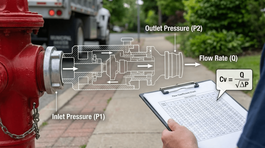
The core of Hydrant Flushers Sizing and Selection: Cv lies in understanding the valve’s hydraulic capacity. The Flow Coefficient (Cv) is defined as the number of US gallons per minute of water at 60°F that will pass through a given valve with a pressure drop of exactly 1 psi.
Engineers must not assume that a “2-inch flusher” from Manufacturer A has the same hydraulic capacity as a “2-inch flusher” from Manufacturer B. The internal geometry, valve type (globe vs. angle vs. diaphragm), and piping configuration drastically alter the Cv. A flusher with a low Cv will restrict flow and may fail to achieve the 2.5 fps required for pipeline scouring, regardless of the upstream system pressure. Conversely, an oversized flusher (excessively high Cv) can rapidly drain a local pressure zone, dropping dynamic pressure below the critical 20 psi threshold. Detailed Cv sizing calculations are provided in the Design Details section below.
The coefficient itself is not specific to flushers. The same definition and the same square-root relationship between flow and pressure drop govern every throttling device in a water system, which is why the sizing method carries over directly from globe valves and other in-line control devices. The difference is the boundary condition. An in-line valve is sized against a downstream pressure the system will hold; a flusher discharges to atmosphere, so the available pressure drop is bounded not by a downstream requirement but by how far the main can be drawn down before violating the minimum residual pressure standard.
Pro Tip: Beware the “Piping vs. Valve” Cv Trap. Manufacturers often publish the Cv of the internal control valve itself, rather than the entire flusher assembly. The overall flusher assembly, including the inlet connection, isolation valve, control valve, dechlorination chamber, and discharge piping, will have a significantly lower effective system Cv than the control valve alone. Always specify that the manufacturer must provide the full-assembly Cv curve for accurate hydraulic modeling.
Installation Environment & Constructability
The physical location of the flusher dictates its structural and installation requirements. Constructability reviews should focus on drainage, freezing conditions, and site integration.
- Drainage and Discharge: Flushed water must go somewhere. If discharging to a storm sewer, ensure an approved air gap is specified to prevent cross-contamination. If discharging to grade, velocity dissipation and erosion control (splash pads, rip-rap) are mandatory to prevent localized flooding and soil erosion.
- Freeze Protection: In cold climates, flushers must be specified as “frost-free.” This typically requires a subsurface installation where the operational valve is located below the frost line, and the unit incorporates an automatic drain valve that empties the vertical standpipe when the main valve closes.
- Space Constraints: Vault-mounted systems require adequate space for maintenance personnel to enter or reach components. Specify minimal clearances around the vault, especially if dechlorination puck feeders are integrated.
Reliability, Redundancy & Failure Modes
Because these devices operate unattended, reliability is paramount. The most common failure mode is a valve that fails to close, resulting in massive, uncontrolled water loss. This is typically caused by debris (sand, pipe scale) clogging the pilot orifice of a diaphragm-actuated valve. To mitigate this, engineers should specify self-cleaning strainers on the pilot control loop and consider piston-actuated valves for systems with high particulate loads.
Another major failure mode is battery depletion. Most automated flushers run on 9V, 12V, or specialized lithium battery packs. Specify low-battery override features that force the valve to fail closed if voltage drops below a critical threshold. Anticipated battery life should exceed one year under typical actuation schedules.
Controls & Automation Interfaces
Modern automated flushers have evolved far beyond simple mechanical timers. Control specifications must align with the utility’s broader smart-grid strategy.
- Local Programmability: Basic units feature handheld bluetooth or infrared programmers. Specify that programmers must be backward compatible and not require proprietary, expensive hardware that forces the utility into a single-source lifecycle.
- Water Quality Optimization: Advanced units trigger flushing based on real-time data from integrated sensors (free chlorine, total chlorine, temperature, turbidity). Specify the calibration intervals and sensor lifespan for these analytical modules.
- SCADA Integration: For critical nodes, specify flushers with cellular, radio (900 MHz), or direct-wired telemetry capable of interfacing with the plant SCADA system via DNP3 or Modbus protocols. This allows operators to initiate remote flushes and monitor valve status.
Maintainability, Safety & Access
Design for the operator. If a flusher requires an excavator to perform routine maintenance, it is poorly designed. Specifications should require that all internal working components, including batteries, solenoids, diaphragms, and pilots, be accessible from above grade without excavation.
Safety considerations must include Lockout/Tagout (LOTO) provisions. Every flusher installation must include an upstream, manually operated isolation valve (curb stop or gate valve) located independently of the flusher enclosure to allow safe depressurization during maintenance. Dechlorination chemical hoppers must be easily accessible to prevent operator ergonomic strain during refill operations.
Lifecycle Cost Drivers
A rigorous Total Cost of Ownership (TCO) analysis will quickly justify the capital expenditure of automated flushers. The primary lifecycle cost driver for manual flushing is labor (vehicle wear, fuel, hourly operator wages, overtime). Automated flushers eliminate these costs.
However, automated flushers introduce their own OPEX requirements: battery replacements, dechlorination tablet consumption, sensor calibration (for smart units), and periodic diaphragm replacement. When evaluating Hydrant Flushers Sizing and Selection: Cv, engineers should require OEMs to submit a 10-year consumable parts cost estimate to ensure utilities are not trapped by inexpensive capital equipment that demands expensive proprietary consumables.
Water loss itself belongs in the same analysis and is frequently omitted. A flusher running 220 gpm for thirty minutes twice weekly discharges roughly 686,000 gallons annually from a single node. At a produced-water cost that includes chemicals, pumping energy, and treatment, a program of twenty such flushers represents a meaningful operating expense and, in water-constrained systems, a defensible reason to move from fixed-interval to sensor-triggered operation.
Comparison Tables
The following tables provide an unbiased engineering framework for comparing different flusher technologies and determining the best fit for specific distribution system applications. Use these matrices to align your project requirements with the appropriate mechanical configuration.
| Technology / Configuration Type | Features & Capabilities | Best-Fit Applications | Limitations & Considerations | Typical Maintenance Profile |
|---|---|---|---|---|
| Above-Ground / Warm Climate | Installed entirely above grade; easy access; gravity discharge to surface; basic timer controls. | Southern climates (no frost); rural dead-ends; areas with ample surface drainage. | Vulnerable to freezing, vandalism, and vehicle impact. Aesthetically visible. | Low. Annual battery replacement; easy visual inspection; simple elastomer swaps. |
| Subsurface / Freeze-Resistant | Valve located below frost line; vertical standpipe with auto-drain feature; often housed in vaults or meter boxes. | Northern climates; urban areas requiring flushers to be flush-to-grade; high-traffic zones. | Susceptible to ground water intrusion; confined space entry may be required; complex to install. | Medium. Requires checking the auto-drain port for blockage; higher risk of pilot tube clogging from soil. |
| Intelligent / Sensor-Triggered | Integrated water quality analyzers (Chlorine/ORP/Temp); SCADA/Cellular telemetry; variable run times based on data. | Critical dead-ends; systems struggling with DBP compliance; hospital/school feeds. | High CAPEX; requires cellular signal or radio mesh; sensors require calibration. | High. Reagents/sensors require replacement/calibration every 3-6 months; battery draw is higher. |
| Temporary / Hydrant-Mounted | Attaches directly to standard fire hydrant 2.5″ NST nozzle; portable; battery-operated timer. | Temporary construction dead-ends; emergency localized water quality events. | Leaves hydrant pressurized (dry-barrel risk); blocks fire access; temporary only. | Low. Easily moved between sites; prone to drops and physical abuse by field crews. |
| Application Scenario | Primary Objective | Required Flow Velocity / Volume | Sizing Priority (Cv focus) | Recommended Automation Type |
|---|---|---|---|---|
| Subdivision Dead-End (Small Main, 2″-4″) | Water Age / Turnover | Low (10 – 30 gpm) | Low Cv. Pressure drop is less critical due to low flow volume required for turnover. | Basic timer, interval-based (e.g., 2 hours, twice a week). |
| Transmission Main Dead-End (Large Main, 8″+) | Sediment Scouring & Turnover | High (400+ gpm) to achieve 2.5 fps | High Cv is critical. Flusher must pass large volumes without excessive head loss. | SCADA-integrated or heavy-duty programmable controller. |
| Low-Pressure Zone (Static < 40 psi) | Turnover while protecting system pressure | Low to Medium (Carefully calculated) | Precision Cv required. Must restrict flow enough to prevent dropping system below 20 psi. | Timer-based with active pressure-monitoring override. |
| Environmentally Sensitive Discharge Area | Regulatory Compliance (Zero Chlorine) | Variable | Moderate Cv. Flow must not exceed the mixing/contact capacity of the dechlorination chamber. | Timer-based with robust solid-puck dechlorination integration. |
Engineer & Operator Field Notes
Theoretical sizing and specification are only half the battle. The successful deployment of Hydrant Flushers Sizing and Selection: Cv relies heavily on proper commissioning, operational strategy, and understanding common field failures.
Commissioning & Acceptance Testing
Do not assume the flusher is functioning optimally just because water comes out. A formal Site Acceptance Test (SAT) should be required in the specification.
- Flow Verification: Use a calibrated pitot gauge or inline flow meter at the discharge point. Compare the measured flow against the calculated theoretical flow based on the unit’s Cv and current system pressure. If flow is substantially lower, suspect an upstream valve is partially closed or the pilot tubing is restricted.
- Pressure Drawdown Test: Connect a pressure logger to the nearest upstream fire hydrant. Initiate a full flushing cycle and verify that the residual pressure in the main does not drop below 20 psi (or the utility’s minimum standard).
- Dechlorination Efficacy: During the flush, take DPD samples of the discharge water at 1 minute, 5 minutes, and 10 minutes. The free/total chlorine must register at 0.0 mg/L to verify that the dechlorination pucks are eroding at the correct rate relative to the flow velocity.
- Fail-Safe Verification: Disconnect the battery or power source during a flushing cycle to verify that the solenoid fails to the closed position.
- Transient Check: Log pressure at high frequency through valve closure, not just during steady flow. A flusher passing several hundred gpm that closes quickly can generate a surge in a small main, and the closure speed is adjustable on most units if the recorded transient is unacceptable.
Common Specification Mistakes
Consulting engineers frequently fall into several specification traps regarding automatic flushers:
- Over-Specification of Pipe Size: Specifying a 2-inch flusher when a 1-inch unit possesses adequate Cv for the required turnover volume wastes capital and increases the risk of excessive pressure transients (water hammer) upon closure.
- Missing Dechlorination Requirements: Under the Clean Water Act, discharging chlorinated water into storm sewers or natural waterways is a violation. Failing to specify integrated dechlorination chambers with chemical feed sizing tied to the Cv and flow rate exposes the utility to severe fines.
- Ambiguous Actuation Specs: Specifying “battery operated” without defining minimum battery life, battery type, and low-power behavior. Specify commercially available, non-proprietary battery configurations where possible.
- Citing Valve Cv Instead of Assembly Cv: Writing a performance clause against the control valve coefficient rather than the complete assembly guarantees a shortfall at startup, because every fitting, strainer, and dechlorination chamber between the tap and the discharge subtracts from the effective figure.
- No Stated Minimum Residual Pressure: A specification that names a required flow without naming the pressure the main must retain has defined only half the hydraulic constraint, and it leaves the utility with no basis to reject an oversized unit.
Common Mistake: Ignoring Drainage Capacity. Engineers often size the flusher perfectly for the distribution main but fail to analyze the receiving infrastructure. If a flusher is sized to output 250 gpm for scouring, but the local storm drain or swale can only handle 100 gpm before flooding adjacent property, the flusher is effectively useless. The physical discharge environment dictates the maximum allowable Cv just as much as the upstream pipe.
O&M Burden & Strategy
Automatic flushers significantly reduce labor, but they are not “set-and-forget” devices. Utilities must implement a preventive maintenance schedule to ensure reliability.
- Routine Inspections (Quarterly): Visually inspect the discharge point for erosion. Check the dechlorination chamber and replenish sodium sulfite or ascorbic acid pucks. Verify that the current program schedule matches seasonal water quality demands.
- Preventive Maintenance (Annually): Replace batteries. For subsurface freeze-resistant models, verify the operation of the auto-drain mechanism before the first freeze. Clean the solenoid pilot screen to prevent the valve from sticking open.
- Predictive Maintenance (3-5 Years): Plan for diaphragm and O-ring replacement depending on chloramine concentrations and sediment loading in the water.
- Seasonal Reprogramming: Water age and residual decay both worsen with temperature, so a schedule set in April is usually wrong by August. Utilities running fixed-interval units should review and adjust run times at least twice a year rather than leaving the commissioning program in place indefinitely.
Troubleshooting Guide
When an operator reports a malfunctioning flusher, the root cause is typically hydraulic or electrical.
- Symptom: Valve will not close (Constant discharge).
Root Cause: Debris has clogged the pilot orifice in the diaphragm chamber, preventing pressure equalization required to force the diaphragm down.
Solution: Isolate the unit, disassemble the control valve cover, and clear the pilot tubing/orifice. Flush the internal screen. - Symptom: Low flow rate / Sputtering discharge.
Root Cause: Upstream isolation valve is partially closed, or the inlet screen is heavily fouled with pipe scale.
Solution: Verify curb stop is fully open; isolate and clean the primary inlet strainer. - Symptom: Unit fails to activate on schedule.
Root Cause: Dead battery, corroded solenoid wire connections, or programming error.
Solution: Check battery voltage under load. Inspect wire nuts for waterproof gel degradation. Re-sync the controller. - Symptom: Chlorine detected in discharge despite full puck hopper.
Root Cause: Flow rate exceeds the contact capacity of the dechlorination chamber, or the pucks have hardened and are no longer eroding at the design rate.
Solution: Verify actual flow against the chamber rating, reduce run flow if the chamber is undersized, and replace hardened pucks. Chamber capacity is a function of flow, not of how much chemical is present.
Design Details / Calculations
The mastery of Hydrant Flushers Sizing and Selection: Cv requires an understanding of fluid mechanics applied to valve operation. The following methodology provides a step-by-step approach to sizing.
Sizing Logic & Methodology
The fundamental equation relating flow (Q), flow coefficient (Cv), and pressure drop (ΔP) for water is:
Where:
Q = Flow rate in US gallons per minute (gpm)
ΔP = Allowable pressure drop across the valve assembly in psi
Cv = Valve flow coefficient
Step-by-Step Sizing Approach:
- Determine Required Flow (Q): First, establish the goal. If the goal is scouring a 6-inch pipe to 2.5 fps, use the pipe cross-sectional area to determine required flow. For 6-inch pipe, Q is approximately 220 gpm. If the goal is simple turnover, calculate the volume of the dead-end and divide by the desired flush duration (e.g., 500 gallons / 30 minutes = 16.6 gpm).
- Determine Available Static Pressure: Obtain the local static pressure from the hydraulic model or field gauge (e.g., 65 psi).
- Calculate Allowable Pressure Drop (ΔP): You must maintain a minimum of 20 psi residual pressure in the main. Therefore, the maximum allowable ΔP is the static pressure minus 20 psi, minus any upstream pipe friction losses during the flow event.
Example: 65 psi (static) − 20 psi (minimum residual) − 5 psi (pipe friction loss at 220 gpm) = 40 psi allowable ΔP. - Calculate Required Cv: Cv = 220 gpm ÷ √40 psi = 220 ÷ 6.32 = 34.8.
- Select the Equipment: You must select a flusher assembly that has a published Cv equal to or greater than 34.8. If the manufacturer’s 2-inch model has a Cv of 42, it is a suitable choice. If their 2-inch model has a Cv of 28, it will restrict flow, act as a bottleneck, and fail to achieve the 220 gpm required for scouring.
Two checks belong at the end of this sequence. First, confirm the selected assembly is not grossly oversized: a unit with a Cv of 80 against a required 34.8 will pass far more than the intended flow if the valve is not throttled, drawing the main down below the residual standard. Second, confirm that the discharge environment can accept the resulting flow, since a hydraulically correct selection that floods an adjacent property is not a usable selection.
Specification Checklist
A robust specification for automated flushers must include the following mandatory clauses:
- Performance: “The complete flusher assembly shall possess a minimum system Flow Coefficient (Cv) of [Calculated Value] and be capable of passing [X] GPM at a pressure drop of [Y] psi.”
- Materials: “All wetted brass components must meet AWWA C800 and NSF/ANSI 372 lead-free requirements. Elastomers shall be constructed of chloramine-resistant compounds.”
- Environmental: “The unit shall incorporate an integrated dechlorination system capable of neutralizing up to 4 mg/L of free/total chlorine at the specified maximum flow rate.”
- Controls: “Controller shall be battery-operated, fully submersible (IP68 rated), and capable of scheduling up to 12 distinct flushing cycles per day.”
- Hydraulic Limits: “The minimum residual pressure in the distribution main during any flushing event shall not fall below [20] psi, verified by pressure logging during site acceptance.”
- Discharge Capacity: “The contractor shall verify that the receiving storm sewer, swale, or grade discharge can accept the specified flow without erosion or off-site flooding, and shall provide velocity dissipation as required.”
- Closure Speed: “Valve closure shall be adjustable, and the resulting pressure transient shall be recorded and demonstrated acceptable during acceptance testing.”
Standards & Compliance
Ensure the equipment complies with the applicable industry standards:
- NSF/ANSI 61 & 372: Mandatory for any component in contact with potable water to ensure no leaching of toxic contaminants or lead.
- AWWA C502 / C503: While these standards primarily cover dry-barrel and wet-barrel fire hydrants, specific material and testing guidelines are often referenced for hydrant-style automatic flushers.
- AWWA C800: Underground Service Line Valves and Fittings, governing the brass and bronze service connection hardware at the tap.
- ASSE 1055: If chemical dispensing (dechlorination) is involved, adherence to cross-connection and backflow prevention standards is critical.
- AWWA M17: Installation, Field Testing, and Maintenance of Fire Hydrants, the practice manual most often referenced for hydrant-mounted and hydrant-adjacent equipment.
Frequently Asked Questions
What does Cv mean in hydrant flusher sizing?
In hydrant flusher sizing, Cv (flow coefficient) represents the hydraulic capacity of the flusher assembly. It is defined as the number of gallons per minute of water at 60°F that will flow through the flusher with exactly a 1 psi pressure drop. A higher Cv means the valve presents less resistance to flow, which is critical when attempting to achieve high-velocity scouring flows in distribution mains.
How do you select between a 1-inch and 2-inch automatic flusher?
Selection should not be based solely on pipe size, but rather on the required flow rate and calculated Cv. If the goal is simply turning over stagnant water to maintain chlorine residuals, a 1-inch flusher with a lower Cv (typically 10-25 gpm) is sufficient. If the goal is pipeline scouring to remove sediment (requiring 2.5 fps velocity), a 2-inch or larger flusher with a high Cv is usually required to handle the higher flow rates (100-300+ gpm) without excessive pressure loss.
What is the typical lifespan of an automated hydrant flusher?
With proper maintenance, the hard casing and piping of an automated flusher can last 15-20 years. Internal wear components, such as elastomer diaphragms and O-rings, typically require replacement every 3-5 years, especially in chloraminated systems. Electronic controllers and solenoids generally have a lifespan of 7-10 years, while batteries must be replaced annually.
Why do automatic flushers fail to close?
The most common reason an automatic flusher fails to close is debris clogging the pilot orifice or pilot tubing of the diaphragm valve. Automatic flushers draw from dead-ends where sediment, rust, and pipe scale accumulate. When the solenoid actuates, this debris can get lodged in the tiny pilot ports, preventing the pressure equalization needed to force the diaphragm closed. Regular cleaning of the internal strainers prevents this issue.
Do I need to dechlorinate the water discharged from a flusher?
Yes, in almost all municipal applications in North America. The Clean Water Act and local environmental regulations tightly restrict the discharge of chlorinated or chloraminated water into storm sewers, streams, or sensitive ecological areas. Flusher specifications must include integrated dechlorination chambers that utilize sodium sulfite or ascorbic acid pucks to neutralize the disinfectant before it enters the environment.
Can hydrant flushers operate during freezing winter months?
Yes, provided you specify a freeze-resistant subsurface model. These units locate the primary control valve and water lines below the local frost line (often in a vault or buried enclosure). When the valve closes, an automatic drain port opens to evacuate any standing water in the vertical discharge riser, preventing ice formation and pipe rupture.
How much water does an automated flushing program use?
More than most utilities estimate before the program starts. A single node flushing 220 gpm for thirty minutes twice a week discharges roughly 686,000 gallons per year, and a twenty-unit program at that duty approaches 14 million gallons annually. That volume carries a real cost in chemicals, pumping energy, and treatment, and in constrained systems it can attract scrutiny during drought restrictions. The usual response is to move from fixed-interval scheduling to sensor-triggered operation, which flushes only when residuals or turbidity actually warrant it and typically cuts volume substantially.
Should the flusher or the storage tank be the first intervention for water age?
Diagnose before specifying. If residuals decay across an entire pressure zone rather than only at the extremities, the problem is usually storage turnover rather than dead-end stagnation, and flushers will chase a symptom at considerable operating cost. Tank level control strategy, inlet and outlet configuration, and mixing all deserve review first in that case. Flushers are the correct intervention where the problem is genuinely localized: dead-end branches, oversized mains serving low demand, and system extremities that no amount of tank management will reach.
Conclusion
Key Takeaways: Sizing & Selection
- Cv is Non-Negotiable: Never size a flusher based merely on connection diameter. Always use the Cv calculation to ensure the assembly can pass the required flow without dropping system residual pressure below 20 psi.
- Define the Duty: Clearly differentiate between low-flow turnover requirements (water age management) and high-flow scouring requirements (sediment removal) before specifying equipment.
- Specify Assembly Cv, Not Valve Cv: The published coefficient for the internal control valve overstates what the complete assembly will pass, and the gap shows up as a failed acceptance test.
- Elastomer Compatibility: Chloraminated distribution systems will rapidly destroy standard rubber seals. Always specify peroxide-cured EPDM or chloramine-resistant synthetic rubbers for internal valve components.
- Environmental Compliance: Fully integrate solid-puck dechlorination systems into the flusher design to avoid Clean Water Act violations when discharging to grade or storm sewers.
- The Discharge Side Sets a Ceiling: A hydraulically correct flow that the receiving swale or storm sewer cannot accept is not a usable selection.
- Lifecycle over CAPEX: Factor in the 10-year OPEX costs of battery replacements, sensor calibrations, replacement diaphragms, and the water itself when selecting a vendor.
The specification of automated equipment in distribution systems requires a rigorous engineering approach. Hydrant Flushers Sizing and Selection: Cv is not simply an exercise in purchasing a valve; it is the process of safely interfacing a pressurized potable water system with the atmospheric environment. Engineers and operators must collaborate to define the hydraulic goals, whether that is gentle turnover to combat water age, or aggressive scouring to remove sediment and biofilm.
By relying on accurate flow coefficient calculations, engineers can avoid the dual pitfalls of oversizing (which threatens system pressure and can induce water hammer) and undersizing (which fails to achieve scouring velocities). Furthermore, careful attention to materials of construction, environmental constraints like freezing and drainage, and the realities of operator maintenance will result in a resilient, high-performing distribution network.
When dealing with highly sensitive hydraulic zones or areas with severe DBP compliance issues, consider consulting directly with hydraulic modeling specialists to simulate the pressure transient impacts of automated flushing. Balancing the competing requirements of water conservation, water quality, environmental compliance, and labor optimization is challenging, but a specification rooted in fundamental hydraulic principles will ensure long-term operational success.