
Valves – Construction Service Installation Mistakes That Cause Leaks
Introduction
In municipal water distribution, wastewater collection, and industrial treatment, fluid containment is the point of the whole system. Yet when commissioning new pipelines or upgrading pump stations, engineers routinely encounter hydrostatic test failures or early leaks, and the cause is usually installation rather than manufacture. A large share of non-revenue water and process spills originates in field execution, improper handling, or flawed interface design rather than in a defective valve.
Most engineers carefully specify valve body materials, pressure classes, and coatings, and overlook the mechanical interfaces during construction. A butterfly valve pinched by misaligned flanges, a resilient-seated gate valve closed onto construction debris, or a control valve carrying the structural weight of adjacent piping will fail regardless of its specification. The results are delayed commissioning, flooded vaults, and lifecycle cost overruns.
This article helps consulting engineers, utility decision-makers, and maintenance supervisors understand the mechanical realities of valve installation. It identifies exact points of failure, sets out installation prerequisites, and provides a framework for specification and commissioning, within the broader context of wastewater treatment valve selection.
How to Select and Specify to Prevent Leaks
Prevention begins long before the contractor mobilizes. Selection criteria must account for how the valve will actually be handled, mounted, and stressed in the field.
Duty Conditions & Operating Envelope
- Pressures including transients: specify not just steady-state conditions but transient spikes. Valves at the end of long runs without surge relief suffer blown gaskets and deformed discs. Pressure class selection must account for surge, not static head alone.
- Operating mode: continuous throttling versus rare isolation dictates the seat type. Using an isolation gate valve for throttling produces high-velocity wire-drawing across the seat and a guaranteed leak regardless of installation quality.
- Future capacity: oversized valves installed for future flows operate near closed, creating localized high-velocity zones that erode seats and cause chronic leakage.
Materials & Compatibility
Material mismatches at the flanged connection are a leading cause of installation failure.
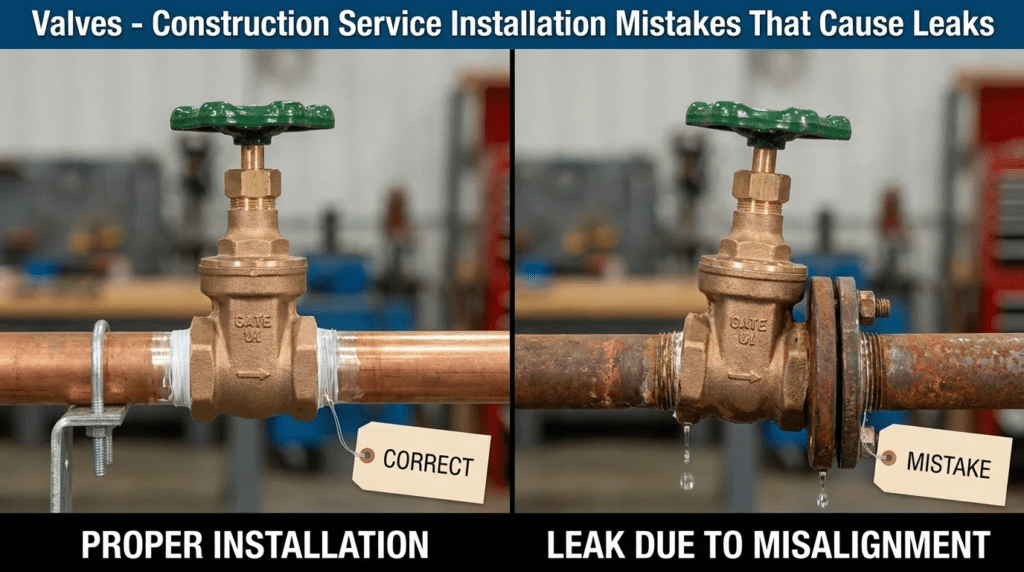
- Flange face compatibility: mating a flat-face cast iron valve to a raised-face steel flange is a severe error. Torquing the bolts makes the raised face impose bending stress on the cast iron flange, which fractures.
- Gasket selection: using ring gaskets on flat-face flanges instead of full-face gaskets concentrates stress and deforms the flange. Chemical compatibility matters equally — standard EPDM in a hydrocarbon-contaminated wastewater line degrades and leaks.
- Galvanic corrosion: installing dissimilar metals without dielectric isolating kits accelerates attack at the joint face and compromises the sealing surface over time.
Hydraulics & Process Performance
- Cavitation: control valves installed with high pressure drops and without anti-cavitation trim lose metal downstream of the seat, eventually producing a through-wall leak.
- Air entrainment: valves on pump suction lines must be airtight. A minor leak admitting air causes pump cavitation, which vibrates the piping, loosens flange bolts, and worsens the original leak.
- Upstream pipe runs: modulating valves generally require several pipe diameters of straight run upstream. Installing a control valve immediately downstream of an elbow produces asymmetric flow that wears the seat and packing unevenly.
Installation Environment & Constructability
- Space and access: confined vaults prevent mechanics from applying a calibrated torque wrench to the bottom bolts of a large valve. Uneven torque produces gasket creep and leakage.
- Structural support: valves are not pipe anchors. Failing to provide independent supports adjacent to heavy valves lets the pipe sag, imposing bending moments at the flanges and opening a gap at the top of the joint.
- Thrust restraint: for buried applications, failing to size thrust blocks or restrained joint lengths behind dead-end valves will push the valve off the pipe during hydrostatic testing.
Reliability, Redundancy & Failure Modes
- Stem packing leaks are very common, usually from failure to adjust the gland during commissioning or, conversely, from over-tightening and scoring the stem.
- Dual isolation: in critical force mains, a single point of isolation is inadequate. Two valves allow one to act as the wear component while preserving the second for tight shutoff.
- Elastomeric seats in resilient gate and butterfly valves typically last well over a decade — unless the valve was installed with the disc partly open during pipe welding, in which case weld slag damages the elastomer permanently on day one.
Controls & Automation Interfaces
- Limit and torque switches: a ubiquitous error is improperly setting the torque switches on an electric actuator. If the close limit switch is miscalibrated and the torque switch is set high, the actuator drives the stem until it bends, the seat fractures, or the bonnet cracks.
- Stroke speeds: actuators set to stroke too quickly cause water hammer, which separates joints and causes leakage elsewhere in the system.
Maintainability, Safety & Access
- Operator access: valves installed well above floor level without permanent platforms or chainwheel operators will not be serviced, and packing glands will dry out and weep.
- Ergonomics: gear operators must be oriented so the handwheel is reachable. Contractors sometimes rotate the valve to fit a space, putting the handwheel against a wall.
- Lockout provisions: isolation valves require verifiable locking mechanisms to establish a zero-energy state for downstream work.
Lifecycle Cost Drivers
- Capital against operating cost: spending on adjustable pipe supports, dismantling joints, and premium gaskets substantially reduces the long-term burden of repairing flange leaks.
- Repair labor: a buried valve leak requires excavation, shoring, dewatering, and repaving. The repair typically costs many multiples of the valve itself.
- Inspection as insurance: specifying certified installers and third-party inspection of torquing procedures generally yields the lowest lifecycle cost.
The Hold Points That Actually Prevent Leaks
Everything above can be written into a specification and still not happen, because a specification describes a requirement while a hold point stops the work until the requirement is demonstrated. Four hold points prevent most installation-induced leakage, and they cost almost nothing to impose.
Hold point one: flange alignment before bolting. The inspector verifies that mating flanges are parallel and concentric within the stated tolerance, without mechanical force having been used to pull them together. This is the point at which a come-along or a hydraulic jack should be visible in the work area and questioned. Pre-stressing a valve body to close a misalignment is the single most damaging thing done to valves in the field, and it is invisible once the bolts are in.
Hold point two: pipeline cleanliness before first closure. The contractor demonstrates that the line has been flushed or pigged and certifies it in writing before any resilient-seated valve is closed. The first closure is when debris gets driven into the seating surface, and it is not recoverable. A signed flush certificate transfers the consequence of skipping this step to the party that skipped it.
Hold point three: witnessed torquing. The contractor submits a torquing procedure in advance, specifying the pattern, the increments, the target value, the wrench calibration date, and the lubricant — because the lubricant changes the relationship between applied torque and achieved bolt load substantially. The inspector witnesses the sequence on a sample of joints. Bolt torque is one of the few things in construction where the correct outcome is unverifiable after the fact without disassembly, which is exactly why it needs witnessing at the time.
Hold point four: actuator setup against physical position. Before acceptance, the actuator is stroked and the limit switch settings verified against the mechanical position indicator on the valve, not against the control system display. A valve reporting closed while the disc sits a few degrees off perpendicular is a seat leak that will be diagnosed three times before someone opens the actuator cover.
Name all four in the specification, assign them to the inspector, and state that work may not proceed past each until signed. The alternative is discovering the same information during hydrostatic testing, at a much higher cost.
Comparison Tables
Table 1: Valve Technologies and Susceptibility to Installation Errors
| Valve Technology | Features & Best Fit | Primary Installation Mistake Causing Leaks | Vulnerability | Maintenance Profile |
|---|---|---|---|---|
| Resilient Seated Gate Valve (AWWA C509/C515) | Clear waterway, bi-directional isolation. Buried water mains and force mains. | Leaving construction debris in the line. The gate drives gravel or pipe shavings into the elastomeric bottom, creating a permanent leak path. | Susceptible to over-tightening with cheater bars, which breaks stems or strips operating nuts. | Low. Occasional exercising and packing adjustment where not O-ring sealed. |
| Butterfly Valve (AWWA C504) | Compact face-to-face, large diameter isolation and basic throttling. | Installing without verifying disc clearance. The disc strikes thick-walled pipe or a reducer, bending and causing seat leakage. | The body seat can be rolled or pinched if flanges are not aligned before bolting. | Medium. Gearbox lubrication and periodic seat inspection. |
| Eccentric Plug Valve | High-solids wastewater and raw sewage; designed to shear through debris. | Installing backwards. These are directional for tight shutoff; seat on the low-pressure side reduces sealing under differential pressure. | Requires specific orientation in horizontal pipe so the plug rotates to the top and grit does not accumulate in the bearing. | Medium. Regular greasing of bearings and journals; packing adjustment. |
| Swing Check Valve (AWWA C508) | Prevents reverse flow; pump discharge headers. | Installing on vertical downward flow, or without adequate upstream straight pipe, causing disc flutter, hinge pin wear, and seat failure. | Susceptible to slamming unless specified with a lever and weight, spring, or air cushion. | High. Hinge pins wear and require replacement to maintain seating. |
| Air Release / Air Vacuum Valve (AWWA C512) | Vents entrained air and breaks vacuum at pipeline high points. | Omitting an isolation valve beneath it for maintenance, or inadequate vent piping, leading to vault flooding when the float fouls. | Requires vertical installation; slight tilt binds the float mechanism and produces continuous leakage. | High. Frequent cleaning, particularly in wastewater service. |
Table 2: Installation Constraint Matrix
| Application | Key Constraints | Highest Leak Risk Factor | Best-Fit Interface Specification | Relative Cost Impact |
|---|---|---|---|---|
| Direct Buried Transmission Main | No visual access, high excavation cost for repair, shifting soils. | Inadequate thrust restraint or settling soil imposing shear stress on joints. | Restrained mechanical joint gate valves or welded connections; properly sized thrust blocks. | Moderate valve / high installation |
| Confined Space Vault | Tight clearance, difficult access, potential submergence. | Inability to torque flange bolts evenly; galvanic corrosion in damp conditions. | Wafer or lug butterfly valves to save space, with dismantling joints for removal without pipe stress. | Moderate |
| Exposed Plant Piping (vibrating) | Pump-induced vibration; thermal movement of long runs. | Vibration loosening flange bolts; thermal expansion loading the valve body. | Flanged valves with restrained dismantling joints or flexible expansion joints to absorb pipe stress. | High, due to accessories |
| High-Solids Sludge Line | Abrasive media, grease buildup, frequent blockage. | Debris settling in the seat area, preventing closure and causing wire-drawing. | Eccentric plug or knife gate valves installed with the stem horizontal to avoid bottom cavity accumulation. | High |
Engineer & Operator Field Notes
Commissioning & Acceptance Testing
- Factory testing: require certified hydrostatic test reports confirming no seat leakage at rated pressure and no shell leakage at the standard’s test pressure. A valve that leaks at the factory will leak in the field.
- Hydrostatic testing: when performing pipeline testing to AWWA C600, the test must load the valve seat. A common mistake is testing with the valve open, which proves only the shell and the flanges. The valve must also be operated under flow and pressure to confirm actuator torque settings.
- Pipeline flushing: the most destructive event in a resilient-seated valve’s life is the first closure. If the line has not been thoroughly flushed to remove rocks, welding slag, and tools, the valve crushes that debris into its seat and the seal is permanently compromised.
Common Specification Mistakes
- Missing torque specifications: “install per manufacturer’s instructions” is inadequate. Require the contractor to submit a flange torquing procedure with a star-pattern sequence, calibrated wrenches, a named lubricant, and inspector witnessing.
- Omitting dismantling joints: without a dismantling joint or flanged coupling adapter next to a large valve in rigid pipe, the contractor uses come-alongs and jacks to pull flanges together. That pre-stresses the valve body and leads to cracking and severe leakage.
- Ambiguous actuator sizing: specifying an actuator without the maximum differential pressure and expected velocity produces either undersized actuators that fail to close fully, causing seat leakage, or oversized actuators that snap stems.
O&M Burden & Strategy
- Valve exercising: valves left static for years scale, and elastomeric seals adhere to the body. A full-cycle exercising program at a defined interval breaks scale, verifies operability, and prevents stem shear when emergency operation is required.
- Packing gland maintenance: most gland leaks resolve by evenly tightening the nuts. Uneven tightening binds the stem and scores it, turning a minor leak into a stem replacement.
- Predictive maintenance: on critical actuated valves, use the actuator’s datalogger to trend torque profiles. Rising torque at the seating position indicates scale buildup or seat swelling and allows intervention before failure.
Diagnosing the Leak
- Flange leak versus shell leak: wipe the area dry and trace the water path with a light and mirror. Water emerging between the flanges points to torque; if torque is correct, the gasket may have failed from a pressure surge or wrong material.
- Packing or stem leak: weeping around the stem indicates loose packing or worn O-rings. If tightening the gland does not stop it, the stem may be bent from actuator misalignment, or scored.
- Seat leak: if the valve is closed but downstream pressure rises or flow persists, the seat is passing. Causes are debris in the invert, damaged elastomer, or a limit switch stopping travel prematurely — check the last of those first, since it is free to correct.
Design Details & Calculations
Sizing Logic
- Velocity constraints: size for fluid velocities in the range of 3 to 8 ft/s for water in sustained service. High velocity across a partially open gate or butterfly valve causes cavitation, vibration, and eventual leakage.
- Flange bolt torque: torque requirements are not universal. They depend on gasket material, bolt grade, and lubrication. The general relationship is T = K × D × F, where T is applied torque, D is nominal bolt diameter, F is the target bolt load, and K is a nut factor that varies substantially with lubrication — which is why the lubricant must be named in the procedure. Over-torquing lubricated bolts stretches them past yield, and a yielded bolt produces a loose flange and a leak.
- Thrust restraint: thrust at a dead-end valve equals internal pressure multiplied by the internal cross-sectional area. A 24-inch valve tested at 150 psi develops roughly 68,000 lb of thrust — the area is about 450 in². Failing to design a thrust block or restrained length to counteract that will push the valve off the pipeline during testing.
Specification Checklist
- Flange alignment tolerance: state that flanges must be aligned within a defined tolerance prior to bolting, without mechanical force used to draw pipes together, and make it a hold point.
- Gasket specification: ring gaskets for raised-face flanges, full-face gaskets for flat-face flanges. Prohibit tape, sealants, or adhesives on flange faces unless approved.
- Fastener specification: exact ASTM designations for bolting, and a named thread lubricant to prevent galling on stainless fasteners and to fix the nut factor used in the torque calculation.
- Installation orientation: specify stem orientation and flow direction for asymmetric valves such as plug and check valves.
- Flush certification: require written certification that the line has been flushed before any resilient-seated valve is closed.
Standards & Compliance
- AWWA C500 series for valve manufacture — C504 for butterfly, C509 and C515 for resilient-seated gate, C508 for swing check, C512 for air valves — and critically AWWA C600 for installation of ductile iron mains and appurtenances.
- ASME B16.1 and B16.5 for flange dimensions and pressure classes. Confirm that class 125/150 flanges are not inadvertently mated to class 250/300, which have different bolt circles.
- NSF/ANSI 61 for potable water service, covering all wetted materials including gaskets and any lubricant used during installation.
Frequently Asked Questions
What is the most common cause of a newly installed flanged valve leaking?
Uneven torque on the flange bolts. Without a calibrated wrench and a star or cross-pattern sequence applied in increments, the gasket compresses unevenly, leaving a gap on the under-torqued side. This is why witnessed torquing is worth imposing as a hold point — the result cannot be verified afterward without disassembly.
How do I select the right gasket?
By flange face and by fluid. Use full-face gaskets on flat-face cast iron valves to avoid flange cracking, and ring gaskets on raised-face steel piping. The material must be compatible with the process fluid — EPDM for water and wastewater, nitrile where hydrocarbon exposure is credible. Never reuse a gasket that has been fully torqued and released.
Why do resilient-seated gate valves leak after hydrostatic testing?
Pipeline cleanliness, almost always. If the line was not thoroughly flushed before testing, rocks, gravel, and pipe shavings are swept into the valve. Closing the gate for the test drives that debris into the rubber seating surface on the wedge, and the seal is permanently damaged.
What is the difference between a shell leak and a seat leak?
A shell leak releases fluid from the pressure boundary to the outside — a cracked body, a blown flange gasket, leaking stem packing. A seat leak is internal: fluid passes through the valve from upstream to downstream while the valve is nominally closed. Seat leaks are most often debris, worn elastomer, or an actuator that is not travelling fully closed.
What does it cost to repair a leaking buried valve?
Far more than the valve. The repair requires excavation, trench shoring, dewatering, cutting out and replacing the valve, backfill, and repaving, and it typically runs to many multiples of the equipment cost. This is the arithmetic that justifies inspection during installation.
Why does a butterfly valve leak past the seat when the actuator reports closed?
Limit switch calibration. If the close limit stops travel before the disc reaches perpendicular, the disc does not fully compress the seat. Recalibrate against the mechanical position indicator on the valve stem rather than against the control system display.
How often should isolation valves be exercised?
At least annually for large municipal isolation valves, and more frequently in corrosive or scaling conditions. Exercising prevents elastomer bonding and clears scale, which is what keeps breakaway torque within the operator’s capacity when an emergency isolation is actually needed.
How does actuator selection interact with installation quality?
Directly — most stem and seat damage attributed to installation is actually an actuator setup or sizing problem, since the actuator is what applies the force that breaks things. Actuator selection and its interface requirements are covered under pneumatic actuated valves, and the supplier landscape across valve types is surveyed in the review of valve manufacturers for water and wastewater.
Conclusion
KEY TAKEAWAYS
- Prevent Flange Stress: valves are not structural anchors. Support adjacent piping independently and use dismantling joints so bending moments never reach the valve body.
- Clean Before Closing: debris is the leading cause of ruined elastomeric seats. Require certified flushing before any resilient-seated valve is operated.
- Make Torquing a Hold Point: uneven tightening cannot be verified after the fact. Require a submitted procedure with a named lubricant, and witness it.
- Match Flange Faces: never mate flat-face cast iron to a raised-face flange. The bending stress fractures the casting.
- Verify Disc Clearance: butterfly and check valve discs must swing fully without striking thick-walled pipe or reducers.
- Check the Actuator Against the Valve: limit switches verified against the mechanical indicator, not the control display.
Specifying the proper valve is half the task. System integrity depends on bridging design engineering and field execution. Understanding the specific mechanisms by which installation produces leaks allows engineers to write specifications that physically prevent the errors rather than describing them.
A leak-free installation requires acknowledging the operating envelope including transients, selecting materials and face configurations that are compatible, accommodating the reality of the installation environment with space for tools and dismantling joints to eliminate pipe strain, and providing thrust restraint where the pipeline is buried. Commissioning must be a documented process with named hold points that proves the integrity of both the seat and the external pressure boundary, rather than a formality performed under schedule pressure.
Where operating parameters are extreme or valves are placed in inaccessible locations, involve valve specialists to review the interface design and mandate third-party inspection during torquing and hydrostatic testing. Weighed against the cost of excavating and repairing a buried leak, the economics of those measures are not close.