
Centrifugal Pumps Wet Well Design and Minimum Submergence to Prevent Vortexing
Introduction
One of the most persistent and costly misconceptions in municipal and industrial water treatment is viewing a wet well merely as a concrete holding tank. In reality, the wet well is a hydraulic structure that dictates the reliability of the pumping equipment. A meaningful share of premature pump failures—often attributed to defective manufacturing—are actually the result of poor intake hydraulics, and chronic vibration and bearing failures in wastewater lift stations frequently trace back to sump geometry rather than to the pump itself.
For engineers responsible for Centrifugal Pumps Wet Well Design and Minimum Submergence to Prevent Vortexing, the challenge lies in balancing civil construction costs with hydraulic requirements. If the wet well is too small or shallow, the pumps will suffer from air entrainment and pre-swirl. If the design is overly conservative, capital costs rise without necessarily improving performance. This tension is where critical specification errors occur.
This discipline applies to every raw water intake, wastewater lift station, and industrial effluent sump. From small duplex package stations to large influent pumping works handling hundreds of millions of gallons per day, the physics remain consistent. The interaction between the fluid and the pump suction bell is governed by specific rules of submergence and geometry. When these rules are violated, the consequences include cavitation, vibration, reduced impeller life, and mechanical seal failure. Within the broader field of centrifugal pumps, intake design is the one area where the civil drawings, not the equipment submittal, determine how long the machine lasts.
This article provides a rigorous, engineer-focused examination of Centrifugal Pumps Wet Well Design and Minimum Submergence to Prevent Vortexing. We will move beyond basic sizing to explore the nuances of ANSI/HI 9.8, the specific mechanisms of vortex formation, and design strategies that ensure lifecycle reliability for critical pumping infrastructure.
How to Select and Specify
Designing a wet well that supports long-term pump health requires a holistic approach. It is not enough to select a pump from a catalog; the engineer must design the environment in which that pump operates. The following selection criteria are essential for achieving optimal Centrifugal Pumps Wet Well Design and Minimum Submergence to Prevent Vortexing.
Duty Conditions & Operating Envelope
The first step in intake design is defining the complete operating envelope. While most specifications focus on the Best Efficiency Point (BEP), wet well hydraulics are most stressed at the extremes of the curve.
- Maximum Flow (Runout): As flow increases, velocity into the suction bell increases. This is the critical point for vortex formation. A design that is stable at BEP may generate strong surface vortices at runout flows.
- Minimum Flow: At low flows, recirculation can occur, but from a wet well perspective, low flow often coincides with low liquid levels. This is where submergence becomes the limiting factor.
- Variable Frequency Drive (VFD) Operation: VFDs allow pumps to operate across a wide range. The wet well design must account for the lowest speed (minimum scouring velocity) and the highest speed (maximum suction inlet velocity).
- Future Capacity: Designing a wet well for Day 1 flows while installing pumps for Year 20 flows is a common error. If the pumps are oversized for current flows, they may cycle frequently or operate at low levels, increasing the risk of air entrainment.
Materials & Compatibility
The physical construction of the wet well influences hydraulic stability and longevity. Smooth surfaces promote orderly flow, while rough, corroded surfaces induce turbulence.
- Surface Roughness: In concrete wet wells, rough finishes exacerbate flow disturbances. Specifications should call for smooth trowel finishes in critical approach channels.
- Microbiologically Induced Corrosion (MIC): In wastewater applications, H2S generation leads to sulfuric acid attack on concrete. Corroded, pitted floors disrupt flow patterns near the floor clearance area, potentially triggering subsurface vortices.
- Baffle Materials: Anti-rotation baffles and splitters are often required to correct flow. These should be fabricated from 316 stainless steel or FRP to withstand the corrosive headspace environment; carbon steel supports fail rapidly and send debris into the pump suction.
Hydraulics & Process Performance
This is the core of Centrifugal Pumps Wet Well Design and Minimum Submergence to Prevent Vortexing. The hydraulic design must ensure uniform flow distribution to the pump impellers.
- Uniform Velocity Profile: The approach flow to the pump should be uniform, steady, and free of swirl. ANSI/HI 9.8 recommends that approach velocity in the pump bay be held low, generally at or below about 1.5 ft/s (0.5 m/s).
- NPSH Available: While minimum submergence is often dictated by vortex prevention, the design must also satisfy NPSH requirements. Calculate NPSH available at the lowest operating level and ensure a margin over NPSH required. These are two separate constraints with two separate governing depths; design to whichever is deeper.
- Air Entrainment: Free-falling water from influent pipes is a primary source of entrained air. Centrifugal pumps tolerate small amounts of air, but performance degrades sharply as the entrained fraction rises, and head loss and instability set in well before the pump loses prime entirely.
Installation Environment & Constructability
Theoretical designs must be constructible. The physical constraints of the site often force compromises that must be mitigated.
- Excavation Depth: Deep wet wells suppress surface vortices well but drive up shoring and dewatering costs. Engineers must weigh a deeper wet well against a larger surface area wet well with lower approach velocities.
- Footprint Restrictions: In retrofit applications where the wet well cannot be expanded, formed suction intakes (FSI) or draft tubes may be necessary to condition the flow within a limited space.
- Fillets and Benching: Square corners are dead zones where solids accumulate and septic conditions develop. Fillets at the floor-wall intersection serve a dual purpose: they direct solids toward the pump suction and eliminate stagnation zones that feed subsurface vortices.
Reliability, Redundancy & Failure Modes
Understanding how intake hydraulics affect failure modes is critical for establishing redundancy.
- Vibration and Bearing Failure: Pre-swirl (rotation of fluid entering the eye) changes the angle of attack on the impeller vanes. This causes local cavitation and unbalanced radial loads, leading to accelerated seal and bearing wear.
- Unbalanced Flow in Multiplex Systems: In systems with three or more pumps, the center pumps often experience different flow conditions than the end pumps. If the influent pipe is perpendicular to the pump lineup, the center pump may receive high-velocity jet flow while end pumps are starved.
- Redundancy: Designing for N+1 redundancy is standard, but the wet well hydraulics must be verified for the all-pumps-running scenario to confirm that peak velocity limits are not exceeded.
Maintainability, Safety & Access
A well-designed wet well requires less manual intervention, reducing operator exposure to hazardous environments.
- Self-Cleaning Geometry: A flat-bottom wet well is a maintenance burden. Trench-type wet wells with sloped entry ramps allow the pumps to scour the floor during each pump-down cycle, reducing the need for vacuum trucks.
- Bar Screen Interface: Automated bar screens must be positioned far enough upstream to allow flow to re-stabilize before reaching the pump intakes. Screen blinding causes uneven velocity profiles that travel downstream to the pumps.
- Confined Space Entry: If baffles or splitters are required, they must be positioned so they do not obstruct personnel access for pump removal or inspection.
Lifecycle Cost Drivers
Total cost of ownership is heavily influenced by the initial hydraulic design.
- Energy Efficiency: A pump suffering from pre-swirl or air entrainment operates off its curve, consuming more energy for less flow. Over a 20-year life, a sustained efficiency loss from poor intake conditions can rival the cost of the pump itself.
- Component Replacement: If improper submergence causes cavitation, impellers may need replacement in a few years rather than lasting a decade or more.
- Civil Works CAPEX: A compliant HI 9.8 intake structure requires more concrete and more complex formwork, but the reduction in maintenance and energy usually recovers the difference well inside the asset life.
The Level Band Is the Design, and Operators Will Move It
Every calculation in this article produces one number that actually matters on site: the pump stop elevation. It is also the single easiest number for anyone to change, from a laptop, without telling the designer. This is where well-designed wet wells get undone.
The pressure to lower it is constant and reasonable-sounding. Lowering the stop elevation increases the effective storage volume between start and stop, which lengthens the run time, reduces starts per hour, and looks like an improvement on every metric an operator watches. Nothing on the HMI indicates that the pump is now running below the depth at which an air-core vortex forms. The damage is cumulative and shows up eighteen months later as a bearing failure.
Three things prevent it. First, make the constraint visible: put the calculated minimum submergence elevation on the station drawing, on a placard at the control panel, and in the O&M manual as a hard limit with the reason stated. “Do not set pump stop below elevation 412.75 — vortex limit” is a sentence that survives staff turnover. Second, resolve the conflict at design rather than leaving it to operations: the required storage volume for acceptable cycling and the required submergence depth are competing demands on the same level band, and if they cannot both be met, the answer is more surface area, a trench configuration, or variable speed — not a lower stop. Third, verify it during commissioning. Run the drawdown test described below, record the elevation where a dye core first appears, and set the low-level alarm from the observed value rather than from the calculation alone.
The same logic applies to the level sensor itself. A submergence limit enforced by a float that has drifted, or by an ultrasonic transducer reading off a grease cap, is not enforced at all. Where the margin between the vortex limit and the pump stop is small, specify redundant level measurement by two different technologies rather than two of the same device.
Comparison Tables
The following tables provide a structured comparison of wet well geometries and vortex classifications. Use Table 1 to select the general layout strategy based on flow and application constraints. Use Table 2 to identify and categorize vortex issues observed in existing installations.
Table 1: Common Wet Well Geometries for Centrifugal Pumps
| Geometry Type | Best-Fit Applications | Hydraulic Features | Limitations & Considerations | Typical Maintenance |
|---|---|---|---|---|
| Rectangular Intake | Standard municipal lift stations, industrial sumps. | Simple approach flow; relies on straight walls to guide fluid. Requires splitters for multiple pumps. | Prone to dead zones in corners. Requires strict adherence to minimum approach lengths. | Moderate. Solids settle in corners unless fillets are installed. |
| Trench-Type Intake | High-solids wastewater, large capacity stations. | Uses a sloped ramp to accelerate flow toward a trench where pump bells are located. Superior self-cleaning. | High civil construction complexity. Sensitive to width sizing, which must maintain scouring velocity. | Low. The cleaning cycle minimizes sludge accumulation. |
| Circular (Caisson) Wet Well | Deep lift stations, small packaged stations. | Structural efficiency for deep excavations. | Hydraulically challenging. Without baffles, the entire volume tends to rotate, creating strong pre-swirl. | High. Difficult to prevent rotation without internal baffles. |
| Formed Suction Intake (FSI) | Space-constrained retrofits, large vertical turbine pumps. | Engineered elbow that conditions flow immediately at the suction, decoupling the pump from wet well hydraulics. | High equipment cost. May require larger hatch openings for installation. | Very low. Eliminates most vortex issues at the source. |
Table 2: Vortex Classification and Severity
| Vortex Type | Visual / Physical Indicator | Surface vs. Subsurface | Severity & Consequence | Mitigation Strategy |
|---|---|---|---|---|
| Type 1 & 2 | Incoherent surface swirl, or a shallow surface dimple. No air entering. | Surface | Negligible. Generally acceptable for most centrifugal pumps. | None required. |
| Type 3 & 4 | Dye core drawn to the intake; vortex pulling floating trash. | Surface | Moderate. Indicates unstable flow. Can intermittently strengthen to Type 5. | Increase submergence or add floating rafts, curtain walls, or baffles. |
| Type 5 & 6 | Air bubbles drawn into the intake; full air core from surface to bell. | Surface | Critical. Causes vibration, loss of prime, noise, and impeller damage. | Raise operating level immediately. Requires structural modification (curtain walls) or a revised level band. |
| Floor/Wall Vortex | Not visible from surface. Detectable via vibration signature or acoustic monitoring. | Subsurface | High. Creates unbalanced loads and cavitation-like erosion on the impeller. | Install floor cones beneath the suction bell, plus floor and wall fillets. |
Engineer & Operator Field Notes
Successful implementation extends beyond the design drawings. The following field notes address commissioning, operational strategies, and troubleshooting.
Commissioning & Acceptance Testing
Verifying hydraulic performance is difficult once the wet well is filled with opaque wastewater. Acceptance testing requires a strategic approach.
- Physical Modeling: ANSI/HI 9.8 calls for a physical model study when the intake geometry departs from the standard layouts, when approach flow is non-uniform or skewed, when pumps are unusually large, or when the consequences of poor performance are severe. Scale model testing is the only way to empirically verify the absence of coherent vortices before concrete is placed. Confirm the current edition’s specific triggers rather than applying a remembered flow threshold.
- Computational Fluid Dynamics: For medium-sized stations, CFD is a cost-effective alternative. The model must be validated and capable of resolving free-surface effects, since a single-phase model cannot predict an air-core vortex.
- Site Acceptance Testing: During startup with clear water where possible, perform a drawdown test. Run the pump at full speed while lowering the wet well level. Observe the surface for vortex formation and record the elevation at which a Type 3 dye core first appears. This becomes the hard low-level alarm setpoint.
Common Specification Mistakes
The following errors appear frequently in municipal bid documents:
- Ignoring Approach Velocity: Specifying the pump correctly but feeding it via a pipe that enters the wet well at high velocity. The jet shoots across the wet well, strikes the back wall, and creates chaotic turbulence at the pump suction.
- Using Sump Volume Only: Sizing the wet well solely on cycle time, to prevent motor overheating, often results in a wide, shallow sump prone to vortexing. A deeper, narrower sump that satisfies both cycle time and submergence is the better outcome.
- Lack of Fillets: Drawing a rectangular box with 90-degree corners guarantees solids deposition and subsurface vortex generation.
- No Stated Level Limit: Omitting the calculated minimum submergence elevation from the drawings and O&M manual, which leaves the most important number in the design undocumented.
O&M Burden & Strategy
- Cleaning Cycles: Grease caps form rigid surfaces that suppress visible vortices while hiding the underlying condition and corrupting level readings. Periodic aggressive cleaning is necessary to keep both the sensor and the effective volume honest.
- Scouring Velocity: Program the controller to perform a scour cycle, pumping down to minimum submergence, during peak flow. Monitor vibration during this cycle; if it exceeds acceptable limits, raise the stop elevation.
- Stop Elevations: Operators often lower the pump stop setpoint to increase effective storage volume. The stop elevation must never encroach on the calculated minimum submergence.
Troubleshooting Guide
If an existing station is experiencing issues, use this diagnostic logic:
- Symptom: Growling noise resembling gravel passing through the pump.
- Probable cause: cavitation or air entrainment.
- Check: Is the noise constant or intermittent?
- Constant: likely suction recirculation, with the pump operating too far left on the curve, or classic NPSH cavitation.
- Intermittent, varying with level: likely vortexing.
- Test: Raise the wet well level by one to two feet.
- If the noise stops, the issue is insufficient submergence causing vortexing.
- If the noise persists, the issue is likely suction recirculation or internal pump damage.
- Interim measure: Floating rafts break surface vortices temporarily. A permanent fix generally requires a curtain wall to lower the effective intake ceiling, floor cones, or a revised level band.
Design Details / Calculations
Precise calculation is the defense against hydraulic instability. The following outlines the methodology for determining minimum submergence per ANSI/HI 9.8.
Sizing Logic & Methodology
The design process begins with the inlet bell outside diameter, D. All critical dimensions are functions of D.
- Determine Inlet Bell Diameter (D). Select a bell diameter such that the inlet velocity falls between roughly 2.0 and 5.5 ft/s (0.6 to 1.7 m/s). Velocity equals flow rate divided by the bell inlet area, in consistent units.
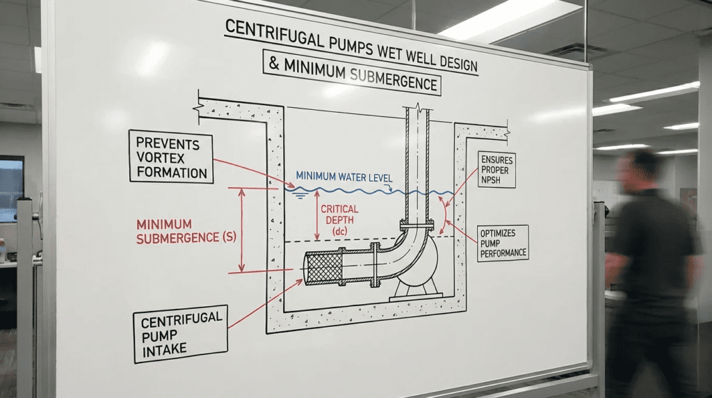
- Calculate Minimum Submergence (S). This is the depth of liquid required above the suction bell lip to prevent surface air-core vortices. The ANSI/HI 9.8 relationship is:
S = D × (1.0 + 2.3 FD)
where FD is the Froude number at the bell inlet:
FD = V ÷ √(g × D)
V is the average velocity at the suction bell inlet, g is gravitational acceleration (32.2 ft/s²), and D is the bell outside diameter. V, D, and g must be in consistent units so that FD is dimensionless.
- Set Floor Clearance (C). The distance from the floor to the bell lip. Target 0.3D to 0.5D. Below 0.3D, entrance losses increase; above 0.5D, subsurface vortex formation under the bell becomes more likely.
- Set Back Wall Clearance (B). The distance from the back wall to the bell centerline. Target 0.75D. If the pump sits too far from the back wall, flow circulates behind the bell and generates strong vortices.
Worked check: for a 24-inch (2.0 ft) bell passing 3,500 gpm, the bell area is 3.14 ft² and the flow is 7.80 ft³/s, giving V = 2.48 ft/s. FD = 2.48 ÷ √(32.2 × 2.0) = 2.48 ÷ 8.02 = 0.309. S = 2.0 × (1.0 + 2.3 × 0.309) = 2.0 × 1.711 = 3.42 ft above the bell lip. Add the floor clearance to convert this to a floor-referenced elevation.
Specification Checklist
- Standard Compliance: “Intake design shall comply with ANSI/HI 9.8, current edition, regarding geometry, submergence, and model study criteria.”
- Fillet Requirement: “Wall-to-floor intersections and corners shall be filleted or chamfered to prevent solids accumulation and vortex formation.”
- Anti-Rotation Devices: “Where approaching flow is non-uniform, a floor splitter or anti-rotation baffle aligned with the pump centerline is required.”
- Level Control: “The pump stop elevation shall be set no lower than the calculated minimum submergence plus a stated safety margin. The limiting elevation shall be shown on the drawings, placarded at the control panel, and recorded in the O&M manual.”
- Commissioning: “A drawdown test shall be performed and the elevation of first observed dye-core vortex formation recorded and used to set the low-level alarm.”
Standards & Compliance
- ANSI/HI 9.8 (Rotodynamic Pumps for Pump Intake Design): the primary standard for geometry, submergence, and model testing criteria.
- ANSI/HI 9.6.6 (Rotodynamic Pumps — Guideline for Pump Piping): governs the piping approaching the wet well, including straight runs and velocity limits.
- ANSI/HI 9.6.1: provides NPSH margin guidance, which must be satisfied independently of the submergence calculation.
- AWWA pump standards (E-series): address the pumps themselves and reference the Hydraulic Institute for intake structure design.
FAQ Section
What is minimum submergence in the context of centrifugal pumps?
Minimum submergence is the vertical distance from the free liquid surface to the inlet of the pump suction bell required to prevent the formation of air-entraining surface vortices. It is distinct from NPSH. NPSH prevents cavitation caused by vapor pressure limits; minimum submergence prevents the physical ingestion of air from the surface. ANSI/HI 9.8 gives the formula based on bell diameter and Froude number, and the two constraints must be checked separately.
How does wet well geometry affect pump performance?
Wet well geometry dictates the flow pattern entering the pump. Poor geometry — sharp corners, excessive width, pumps located too far from walls — causes non-uniform velocity profiles and pre-swirl. This turbulence reduces pump efficiency, causes vibration, accelerates bearing wear, and can produce cavitation damage on the impeller, shortening mean time between failures substantially.
What is the difference between surface and subsurface vortices?
Surface vortices form at the liquid surface and extend downward; if strong enough, they draw air into the pump. Subsurface vortices originate at the floor or walls of the wet well and enter the bell from below. Subsurface vortices do not entrain atmospheric air, but they create low-pressure cores that cause localized cavitation and severe vibration. Both are destructive and require different mitigation: deeper water for surface vortices, floor splitters and cones for subsurface vortices.
Why is the Froude number important for intake design?
The Froude number is a dimensionless ratio of inertial to gravitational forces. In intake design it quantifies the tendency toward vortex formation: a higher value indicates higher bell inlet velocity relative to the characteristic depth, increasing vortex risk. ANSI/HI 9.8 uses it as the primary variable in the minimum submergence calculation, which is why bell sizing and submergence cannot be decided independently.
Can I use a vortex breaker to fix an existing problem?
A vortex breaker attached to the suction bell can disrupt a vortex core, but it does not correct poor approach flow or inadequate submergence. In wastewater service these devices collect rags, which can block flow and starve the pump. The preferred solution is correcting the wet well geometry or the operating level band.
How close should the pump be to the wet well floor?
Per ANSI/HI 9.8, floor clearance from the floor to the suction bell lip should generally be between 0.3D and 0.5D, where D is the bell outside diameter. Below 0.3D, entrance losses increase and can affect NPSH available. Above 0.5D, the risk of subsurface vortices forming under the bell rises significantly.
How does intake design connect to the pump’s operating cost?
Directly, and the effect is permanent. A pump running with pre-swirl or entrained air sits off its published curve for its entire service life, so the penalty compounds every hour the station runs. That interaction is quantified in the analysis of centrifugal pumps lifecycle cost, and the mechanisms behind the losses are covered in more depth under cavitation in centrifugal pumps and efficiency of centrifugal pump selection.
Conclusion
KEY TAKEAWAYS
- Submergence is Calculated, Not Guessed: Use the ANSI/HI 9.8 relationship based on bell diameter and Froude number. Manufacturer data sheets often list only the submergence needed to avoid mechanical air binding.
- Geometry Matters: Adhere to the 0.75D back-wall clearance and 0.3D–0.5D floor clearance. Deviating creates dead zones and swirl.
- Velocities Must Be Low: Approach velocity in the bay should stay at or below about 1.5 ft/s; bell inlet velocity below about 5.5 ft/s.
- Document the Level Limit: The pump stop elevation is the design. Put it on the drawings, on a placard, and in the O&M manual, with the reason stated.
- Avoid Day 1 Oversizing: Designing for large future flows produces low velocities and settling today. Use variable speed or staged implementation.
- Air is the Enemy: Entrained air degrades head and efficiency well before the pump loses prime. Adequate submergence is the only reliable prevention.
The success of any pumping station is defined before the first cubic yard of concrete is poured. Centrifugal Pumps Wet Well Design and Minimum Submergence to Prevent Vortexing is not a box-checking exercise; it is an engineering discipline that correlates directly to the lifecycle cost and reliability of the facility.
Engineers must advocate for proper hydraulic design even when it competes with structural economies. A slightly deeper excavation, or the inclusion of fillets and baffles, carries a minor upfront cost compared with decades of clearing air-bound pumps, replacing cavitated impellers, and managing chronic vibration. By applying ANSI/HI 9.8, documenting the limiting level, and verifying it at commissioning, engineers can deliver infrastructure that operates reliably and quietly for generations.