
Multi-Stage Water Filtration Systems: 2-Stage to 7-Stage Compared
Introduction to Multi-Stage Water Filtration
One of the most frequent and costly specification errors in industrial and municipal water treatment is the misalignment of multi-stage filtration trains with the specific influent water profile. Over-engineering a system with redundant stages unnecessarily inflates capital expenditure (CAPEX) and creates parasitic pressure losses. Conversely, under-engineering a system virtually guarantees premature membrane fouling, excessive consumable replacement costs, and unacceptable downtime. The key to optimal design lies in mastering Multi-Stage Water Filtration Systems: 2-Stage to 7-Stage Compared. Proper configuration requires a deep understanding of target effluent quality, Silt Density Index (SDI), Empty Bed Contact Time (EBCT), and trans-membrane pressure (TMP) thresholds.
Stage counting only makes sense once the underlying separation mechanisms are understood, since a “stage” is simply one unit operation in series. The overview of different types of water filtration systems establishes those mechanisms — straining, adsorption, membrane separation, ion exchange, and disinfection — and it is worth fixing them before counting stages. A seven-stage system built from poorly chosen mechanisms will underperform a well-designed four-stage train, because stage count measures sequence length rather than treatment capability.
The engineering landscape of multi-stage filtration spans municipal drinking water plants, industrial process water generation, high-purity laboratory setups, and wastewater effluent polishing. By strategically stringing together varying technologies—from basic physical straining to molecular-level separation and advanced oxidation—engineers can build a robust barrier against fluctuating source water conditions. This pillar page comprehensively details the varying configurations, from baseline dual-stage units to advanced ultra-purification trains, alongside the distinct process stages and application-specific packaged systems that dictate modern water treatment design.
Subcategory Landscape — Types, Technologies & Approaches
Navigating multi-stage filtration requires engineers to evaluate three interconnected dimensions: the system configuration (number of stages), the unit operations (the technologies acting as stages), and the application context. The following sections detail the primary branches of multi-stage filtration. Each subcategory acts as a critical building block in plant design; understanding their individual capabilities, physical limitations, and integration requirements is paramount for specifying reliable treatment trains.
2-Stage Filtration Systems
2-stage filtration systems represent the baseline of multi-stage treatment, typically comprising a physical barrier followed by a chemical adsorption step, such as a 5-micron spun polypropylene filter followed by granular activated carbon (GAC). In industrial environments, these are specified primarily as pre-treatment guards for downstream equipment rather than standalone purification systems. They are utilized when source water has a relatively low Total Dissolved Solids (TDS) load but requires targeted removal of suspended solids and free chlorine to prevent oxidative damage to subsequent processes. Their main advantage is an extremely low CAPEX and minimal pressure drop (typically < 5-10 psi delta), making them suitable for low-pressure municipal tie-ins. However, their limitation is a complete inability to reduce dissolved mineral content or manage high biological loading. Engineers must size these systems carefully based on EBCT for the carbon stage to ensure sufficient chlorine scavenging.
3-Stage Filtration Systems
Building upon the dual-stage concept, 3-stage filtration systems typically introduce a second barrier of either finer sediment filtration, a denser carbon block, or a coarse membrane layer (like ultrafiltration). A standard industrial configuration might include a 5-micron pre-filter, a GAC vessel, and a 1-micron absolute pleated filter to capture carbon fines before they reach delicate downstream valves or instruments. These systems are widely deployed in commercial HVAC makeup water, cooling tower side-stream filtration, and light industrial process water. The primary advantage is increased protection against particulate breakthrough, offering significantly higher reliability than two-stage setups. A critical specification consideration is monitoring the differential pressure (dP) across three sequential housings, which generally requires intermediate pressure gauges to isolate the fouled stage during troubleshooting.
This is the most commonly installed configuration in residential and light commercial service, and a dedicated treatment of the three stage water filtration system covers the point-of-entry and point-of-use variants at that scale — cartridge sizing, housing standards, and the replacement intervals that determine whether the train actually performs as specified. The engineering logic is identical to the industrial case; what differs is that nobody is monitoring differential pressure, so the sequence depends on scheduled replacement rather than on measured breakthrough.
4-Stage Filtration Systems
4-stage filtration systems generally mark the transition into membrane separation, commonly arranged as sediment pre-filtration, carbon adsorption, a reverse osmosis (RO) or nanofiltration (NF) membrane, and a post-treatment polishing filter. These configurations are standard in boiler feedwater pretreatment and critical manufacturing processes where TDS reduction is mandatory. The addition of the membrane stage shifts the operational paradigm from simple flow-through filtration to cross-flow separation, requiring concentrate (reject) management and booster pumps to overcome osmotic pressure. Advantages include robust reduction of dissolved solids, heavy metals, and organics. However, the pre-treatment stages (stages 1 and 2) must be strictly sized to maintain an SDI of < 3.0 to protect the stage 3 membrane, making feed water profiling the most critical factor in their specification.
5-Stage RO Filtration Systems
The 5-stage RO filtration systems are the workhorses of both high-end commercial and standard industrial water purification, typically sequenced as: coarse sediment, GAC, carbon block (or fine sediment), RO membrane, and a final activated carbon polishing stage. This architecture provides redundant protection for the RO membrane by using dual organic and chlorine scavenging stages, which is critical when drawing from heavily chlorinated municipal sources that experience seasonal chloramine dosing. These systems are highly suitable for electronics manufacturing wash water, beverage production, and municipal desalination pre-treatment. The key advantage is extended membrane life and consistent permeate quality. Engineers specifying these systems must account for the steady-state pump requirements (often multi-stage centrifugal pumps) to maintain the 150-400 psi typically needed for industrial membrane flux rates.
6-Stage Advanced Filtration Systems
6-stage advanced filtration systems incorporate specialized final treatments, typically adding ultraviolet (UV) sterilization or targeted remineralization to a standard 5-stage chassis. These systems are strictly specified for applications where biological control of the permeate is critical, or where the aggressive nature of RO permeate (low pH, high corrosivity) would damage downstream piping. Typical applications include pharmaceutical wash water, food and beverage ingredient water, and advanced municipal direct potable reuse (DPR) pilots. The major advantage is comprehensive control over both chemical and biological effluent parameters. However, engineers must properly size the UV stage based on the specific UV transmittance (UVT) of the water and ensure the system maintains a minimum velocity to prevent thermal build-up inside the UV reactor chamber during low-demand periods.
7-Stage Ultra-Purification Systems
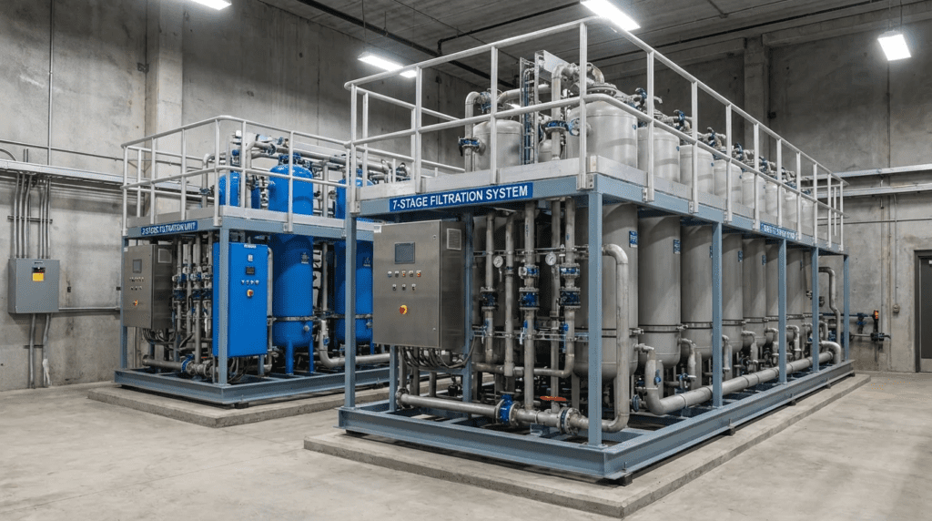
Representing the apex of commercial and industrial water treatment, 7-stage ultra-purification systems combine mechanical, chemical, membrane, and electromagnetic technologies. A typical train might involve: sediment, GAC, anti-scalant dosing, RO membrane, mixed-bed deionization (DI), UV sterilization, and sub-micron final absolute filtration. These are engineered explicitly for semiconductor fabrication, power generation (boiler feed), and high-tier pharmaceutical water-for-injection (WFI) generation. The primary advantage is the reliable production of 18.2 Megohm-cm ultrapure water. The limitations are exceptionally high CAPEX, intense operational monitoring requirements, and high consumable costs. Specifications must strictly adhere to ASTM D1193 Type I or Type II standards, with continuous inline resistivity and Total Organic Carbon (TOC) monitoring interlocked with the plant’s SCADA system.
Sediment Pre-Filtration Stages
Focusing on the components within these systems, sediment pre-filtration stages act as the primary defense mechanism against total suspended solids (TSS), turbidity, and colloidal matter. Technologies range from multi-media sand filters and automated screen filters in large-scale municipal plants to melt-blown polypropylene depth cartridges in packaged industrial skids. They are deployed at the very beginning of the treatment train. Their primary function is lowering the Silt Density Index (SDI) to protect downstream pumps and membranes from abrasive wear and particulate fouling. Selection relies heavily on particle size distribution (PSD) analysis of the feed water; engineers must decide between nominal or absolute micron ratings and surface versus depth filtration mechanisms to optimize dirt-holding capacity and backwash or replacement frequencies.
Activated Carbon Absorption Stages
Activated carbon absorption stages are dedicated to the removal of free chlorine, chloramines, volatile organic compounds (VOCs), and dissolved organics. In industrial settings, this is typically achieved through large fiberglass or steel pressure vessels packed with granular activated carbon (GAC), though smaller flow systems may utilize extruded carbon blocks. This stage is universally required upstream of polyamide thin-film composite (TFC) RO membranes, which will permanently degrade upon exposure to even trace amounts of free chlorine (typically >0.1 ppm). The critical specification factor is Empty Bed Contact Time (EBCT); standard chlorine removal requires 2-3 minutes of EBCT, while chloramine removal demands specialized catalytic carbon and 5-10 minutes of EBCT. Backwash rates must also be calculated to achieve a 30-40% bed expansion without washing media down the drain.
Membrane Separation Stages
The heart of advanced multi-stage trains, membrane separation stages—encompassing Reverse Osmosis (RO), Nanofiltration (NF), and Ultrafiltration (UF)—utilize semi-permeable materials and hydrostatic pressure to separate dissolved solids and pathogens from the water matrix. UF is often used for surface water treatment and RO pre-treatment, while RO and NF are deployed for desalination, heavy metal removal, and softening. Their advantage is the physical removal of contaminants down to the ionic level without the use of chemical regenerants (unlike ion exchange). Design engineers must rigorously calculate mass balance, system recovery rates (typically 75-85% for industrial RO), and membrane flux (gallons per square foot per day, or GFD). Temperature drastically impacts these calculations; colder water increases viscosity, necessitating variable frequency drives (VFDs) on high-pressure pumps to maintain constant permeate flow.
Deionization and Polishing Stages
For applications requiring zero TDS, deionization and polishing stages are placed downstream of membrane systems to capture the trace ions that slip through RO membranes. This is achieved using ion exchange resins—either separate bed (cation/anion) or mixed bed systems, or through continuous electrodeionization (CEDI) modules. They are predominantly used in power plant boiler makeup, microelectronics, and laboratory water systems. While traditional resin beds require hazardous chemical regeneration (HCl and NaOH), modern CEDI utilizes direct current to continuously regenerate the resin internally, offering a safer and more consistent operational profile. Proper specification demands precise feed water profiling; CEDI modules will fail rapidly if fed with water containing hardness above 1.0 ppm as CaCO₃ or silica above 0.5 ppm, making the upstream RO stage’s performance critical.
Ultraviolet (UV) Sterilization Stages
Ultraviolet (UV) sterilization stages utilize 254 nm wavelength light to inactivate bacteria, viruses, and protozoa by disrupting their cellular DNA. Placed at the tail end of multi-stage systems or on recirculation loops, UV provides chemical-free disinfection without creating harmful disinfection byproducts (DBPs) like trihalomethanes. They are universally applied in pharmaceutical water, food processing, and high-purity loops where residual chlorine is forbidden. When specifying UV, engineers must calculate the required dose (expressed in mJ/cm²), which is a function of flow rate, reactor geometry, and the water’s UV Transmittance (UVT). Water with high iron, hardness, or organics will foul the quartz sleeves, meaning UV stages must be protected by preceding filtration and softening stages to remain effective.
Remineralization and Alkalization Stages
Post-RO water is notoriously aggressive, typically exhibiting a pH of 5.5 to 6.5 and possessing zero buffering capacity, making it highly corrosive to metal piping infrastructure. Remineralization and alkalization stages solve this by passing the permeate through sacrificial beds of calcite (calcium carbonate) or magnesium oxide media, or via precise chemical dosing of caustic soda or lime. These stages are heavily utilized in municipal desalination plants prior to distribution, and in beverage plants to achieve specific flavor profiles. The engineering challenge lies in calculating the Langelier Saturation Index (LSI) to ensure the final blended water is slightly scaling rather than corrosive. Bed-based remineralization requires calculating dissolution rates, which fluctuate based on the temperature, pH, and flow rate of the incoming RO permeate.
Boiler Feedwater Multi-Stage Systems
Looking at application-specific packages, boiler feedwater multi-stage systems are engineered to prevent catastrophic scale formation and corrosion inside high-pressure steam boilers. A standard setup might include a 4- or 5-stage configuration: multi-media filtration, softening, RO, and a final polishing dealkalizer or CEDI stage. The specific configuration depends entirely on the boiler operating pressure; low-pressure boilers (<150 psig) may only require softening, whereas high-pressure power generation boilers (>1,000 psig) demand complete demineralization via 7-stage systems. Specification errors here are financially devastating; failing to remove silica and hardness leads to scale that insulates boiler tubes, drastically reducing thermal efficiency and eventually causing tube rupture. Engineers must align the multi-stage system’s effluent quality strictly with ASME boiler water guidelines.
Wastewater Effluent Polishing Systems
In the context of water reuse, wastewater effluent polishing systems apply multi-stage filtration to secondary or tertiary clarifier effluent, upgrading it for industrial reuse or environmental discharge. These systems typically utilize a 3- to 4-stage configuration: automatic screen filtration, Ultrafiltration (UF), followed by Reverse Osmosis (RO) and UV disinfection. These trains are utilized heavily in zero liquid discharge (ZLD) plants and municipal indirect potable reuse (IPR) projects. The primary limitation and operational headache is profound organic and biological fouling. Therefore, design engineers must specify robust UF membranes that can withstand frequent aggressive clean-in-place (CIP) protocols using sodium hypochlorite, and must incorporate comprehensive pretreatment coagulation and flocculation to manage high total suspended solids (TSS).
High-Purity Laboratory Water Systems
High-purity laboratory water systems are compact, highly sophisticated multi-stage units designed to meet stringent clinical and analytical standards (e.g., CLRW, ASTM Type I-III). Typically built as 6- or 7-stage all-in-one benchtop or wall-mounted units, they utilize pre-filtration, RO, dual-wavelength UV (185nm for TOC reduction and 254nm for sterilization), and highly specialized ultra-polishing resin cartridges. These are found in healthcare diagnostics, HPLC analysis, and semiconductor research. The critical differentiator is the requirement for almost zero dead-legs in the piping and continuous internal recirculation to prevent bacterial proliferation. Engineers must size these not just for daily volume, but for instantaneous peak draw, often requiring pressurized high-purity storage bladders.
Selection & Specification Framework
Choosing the correct multi-stage configuration requires an empirical, data-driven framework. The number of stages and the technologies utilized should never be guessed; they are mathematically derived from a comprehensive feed water analysis mapped against required effluent specifications.
Decision Tree Logic
The primary driver for selecting between a 2-stage to 7-stage system is the target water quality standard. If the goal is simply equipment protection from large debris and chlorine, two-stage systems are adequate. If the process requires the removal of dissolved minerals (TDS), the system must step up to at least four stages to incorporate membrane technology. When sub-parts-per-million purity or ultrapure water is required, engineers must specify seven-stage trains incorporating deionization and UV.
- Step 1: Feed Water Analysis. Analyze TSS, TDS, pH, hardness, silica, organics (TOC), and free chlorine. High TSS pushes the design toward robust sediment pre-filtration stages; high chlorine mandates larger activated carbon absorption stages.
- Step 2: Define Effluent Requirements. Is it potable water, boiler feed (ASME standards), or microelectronics (ASTM Type I)?
- Step 3: Select the Separation Engine. Based on the TDS requirement, select the core technology (typically membrane separation stages for bulk reduction).
- Step 4: Build Pre-Treatment. Work backwards from the membrane. What degrades the membrane? (Chlorine, scaling ions, particulates.) Assign a stage to mitigate each threat.
- Step 5: Build Post-Treatment. Work forward from the membrane. Does the permeate need polishing, sterilization, or pH adjustment? Add deionization and polishing stages or remineralization and alkalization stages as needed.
Three further resources sharpen this framework. Comparative guidance on water filtration system cost covers how capital and recurring costs distribute across configurations — relevant because each additional stage adds a consumable line item that compounds annually. Coverage of commercial water filtration systems addresses the middle scale where these configurations are most common, and a survey of water filtration system brands covers who supplies them once the stage count and technology set are settled.
Worked Example — When the Sixth Stage Pays and When It Doesn’t
A beverage facility uses 40 gpm of RO permeate and is deciding whether to add UV and remineralization to an existing five-stage train.
- UV stage: 40 gpm reactor, roughly $6,000 installed, with annual lamp and sleeve maintenance around $900
- Calcite remineralization: roughly $9,000 installed, with media replacement around $1,400 per year
- Combined: $15,000 capital and about $2,300 per year recurring
- Avoided cost: a single microbial excursion causing a batch rejection at this facility runs $40,000–70,000
The UV stage justifies itself on a single avoided event across its life, and in a product-contact application the decision is effectively automatic. Remineralization is different: it earns its place if the permeate contacts carbon steel or copper downstream, or if product flavor profile depends on mineral content. Where the permeate goes straight into a stainless or plastic loop and is subsequently blended, the stage may be spending $1,400 a year to solve a problem that does not exist.
The general test is whether each stage addresses a named, specific failure mode. “Extra protection” is not a design basis. Where a stage cannot be tied to a contaminant present in the feed analysis or a material exposed downstream, it is adding pressure drop, footprint, and a consumable line item in exchange for nothing measurable.
Lifecycle Cost Trade-offs (CAPEX vs OPEX)
Adding stages increases CAPEX but frequently decreases OPEX by protecting high-value downstream components. For instance, skipping fine sediment pre-filtration stages upstream of an RO membrane lowers initial capital cost marginally but sharply increases RO membrane replacement frequency due to fouling. Similarly, employing a three-stage configuration instead of two introduces an extra cartridge filter that costs money to replace, but it drastically extends the life of costly RO elements. The specification should balance the labor burden of consumable replacements against the footprint and energy costs of complex multi-stage pumping.
Comparison Tables
The following tables provide an engineering quick-reference map. Table 1 outlines the features and limitations of the primary multi-stage configurations and technologies. Table 2 aligns specific industrial applications with their optimal filtration configuration.
Table 1: Subcategory Technology & Configuration Comparison
| Type / Technology | Key Features | Best-Fit Applications | Limitations | Relative CAPEX | Maintenance Profile |
|---|---|---|---|---|---|
| 2-stage filtration systems | Sediment + carbon physical barriers | Light commercial, low-spec guard filters | Cannot remove dissolved solids/TDS | Low | Frequent cartridge swap (monthly) |
| 4-stage filtration systems | Adds basic RO/NF membrane separation | Standard boiler feed, municipal desalination | Requires pressure boosters, creates reject wastewater | Medium | Quarterly pre-filters, 3-5 yr RO membranes |
| 5-stage RO filtration systems | Redundant carbon/sediment + RO + post-polish | Heavy industrial process, heavy chloramine loads | Larger footprint, higher cumulative pressure drop | Med-High | Moderate labor; high consumable tracking |
| 7-stage ultra-purification systems | Includes DI, UV, and sub-micron polishing | Semiconductor, pharma WFI, high-pressure boiler | Highly complex, strict operational tolerances | Very High | High; requires specialized instrumentation tech |
| Activated carbon absorption stages | High surface area adsorption | Chlorine and organics removal pre-RO | Prone to biological fouling if idle | Varies | Backwashing, media rebedding every 1-3 yrs |
| Ultraviolet (UV) sterilization stages | 254nm pathogenic DNA disruption | Zero-chemical disinfection loops | Ineffective in high turbidity/low UVT water | Medium | Annual lamp swap, quartz sleeve cleaning |
Table 2: Application Fit Matrix
| Application Scenario | Best-Fit Subcategory | Key Constraints & Requirements | Operator Skill Impact |
|---|---|---|---|
| Low-pressure steam boiler makeup (<150 psig) | 4-stage filtration systems | Hardness removal critical; TDS reduction improves blowdown rates | Basic; manage softener salt and RO filters |
| High-pressure power generation boiler (>1,000 psig) | 7-stage ultra-purification systems | Silica < 10 ppb; requires deionization and polishing stages | Advanced; requires resin chemistry knowledge |
| ZLD wastewater recovery | Wastewater effluent polishing systems | High bio-fouling risk; demands robust UF pre-treatment | Advanced; frequent CIP execution |
| Clinical diagnostic lab water | High-purity laboratory water systems | Continuous recirculation required to meet CLRW standards | Moderate; system largely automated, cartridge based |
Engineer & Operator Field Notes
Translating multi-stage design into operational reality requires understanding how varying subcategories behave in the field. Requirements shift dramatically from a simple mechanical skid to a dynamic, chemically dependent ultra-purification train.
Commissioning Considerations
Commissioning protocols vary heavily depending on the stages included. For systems utilizing activated carbon absorption stages, initial flushing is critical to remove carbon fines. If an engineer prematurely opens the valve to the downstream membrane separation stages before the carbon effluent runs clear, the carbon fines will instantly blind the RO membrane face, destroying it on day one. For systems with deionization and polishing stages, especially CEDI, the modules must be purged of all air and slowly ramped up in voltage while monitoring flow to prevent localized boiling and internal melting of the resin spacers.
Common Specification Mistakes
A prevalent error is neglecting cumulative pressure drop. Engineers specifying five-stage RO systems sometimes size the feed pump based solely on the RO membrane’s required operating pressure, forgetting that the preceding three pre-treatment housings might introduce a 15-25 psi delta. This starves the high-pressure pump, leading to cavitation. Another critical error occurs when specifying remineralization and alkalization stages: failing to account for the empty bed contact time required for calcite dissolution, which is much longer in cold water. Specifying a vessel that is too small leads to inadequately buffered water entering the plant’s piping network.
Never specify a multi-stage system without sample taps and pressure gauges between every stage. When a six-stage train experiences low permeate flow, the operator must be able to isolate the pressure drop across each individual housing to determine which filter or membrane is fouled.
O&M Comparison Across Subcategories
Which subcategories require the most daily operator attention versus which are hands-off? Systems relying heavily on physical cartridge barriers (two- and three-stage configurations) are highly predictable; maintenance is a function of totalized flow or differential pressure, requiring basic mechanical skills to swap cartridges. Conversely, wastewater effluent polishing systems utilizing UF and RO demand high operator attention to monitor trans-membrane pressure (TMP) curves and execute complex chemical Clean-in-Place (CIP) procedures.
Typical maintenance intervals diverge significantly:
- Sediment pre-filtration stages: replaced or backwashed daily to weekly depending on solids loading.
- Ultraviolet (UV) sterilization stages: require virtually no daily labor, but mandate an annual lamp replacement and quartz sleeve acid-cleaning.
- Consumable costs scale linearly with the number of stages. Seven-stage trains carry the highest OPEX due to the frequent exchange of polishing resins and sub-micron final filters, alongside standard RO membrane replacements (typically every 3 to 5 years).
Troubleshooting Overview
Troubleshooting must be approached systematically by stage:
- Symptom: rapid RO membrane fouling. Root cause: failure in the sediment pre-filtration stages (bypassing due to a torn O-ring) or exhaustion of the activated carbon absorption stages leading to chlorine oxidation of the membrane.
- Symptom: high TOC in ultrapure water. Root cause: failure of the 185nm UV destruct stage, or exhausted anion resin in the deionization and polishing stages.
- Symptom: decreased permeate flow with normal pump pressure. Root cause: membrane scaling (calcium or silica) due to failed upstream anti-scalant dosing or softening, common in improperly monitored boiler feedwater multi-stage systems.
Municipalities often switch from free chlorine to chloramines seasonally. Standard GAC sized for 2 minutes of EBCT will not remove chloramines. This leads to immediate breakthrough and RO membrane oxidation. Ensure your activated carbon absorption stages are sized for 5+ minutes of EBCT or utilize catalytic carbon if chloramines are present.
Design Details & Standards
Rigorous mathematical modeling and adherence to international standards are non-negotiable when engineering multi-stage filtration solutions.
Sizing Methodology Overview
Sizing is fundamentally driven by flux (flow per unit area) and contact time. For membrane separation stages, the design flux J is calculated as J = Q ÷ A, where Q is the permeate flow rate and A is the active membrane area. Industrial RO systems are typically designed for a flux of 10-15 GFD on municipal feed, and 15-20 GFD on RO permeate (in double-pass systems). Pushing flux higher leads to exponential fouling rates.
Key Design Parameters by Subcategory
Design parameters shift based on the selected configuration. For activated carbon absorption stages, the critical metric is Empty Bed Contact Time: EBCT (min) = bed volume ÷ flow rate. When specifying a five-stage RO train, engineers must calculate the osmotic pressure of the feed water to size the high-pressure pump, approximated as osmotic pressure (psi) ≈ TDS (ppm) ÷ 100. For ultraviolet (UV) sterilization stages, the sizing parameter is UV dose (mJ/cm²), which must account for the end-of-lamp-life degradation factor, typically designing for 30-40 mJ/cm² for standard municipal disinfection, or up to 120 mJ/cm² for virus inactivation in wastewater effluent polishing systems.
Applicable Standards & Compliance
Multi-stage systems span municipal, industrial, and consumer regulatory frameworks depending on scale and duty. Wetted components in drinking water service require NSF/ANSI 61 with NSF/ANSI 372 for lead content, while packaged residential and light commercial units are certified against NSF/ANSI 42 (aesthetic effects), 53 (health effects), 58 (reverse osmosis), 55 (ultraviolet systems), and 401 (emerging contaminants). Laboratory water follows ASTM D1193 and CLSI guidance for clinical reagent water. Media quality follows AWWA B100 for filter material and B604 for granular activated carbon. Municipal finished water must meet the National Primary Drinking Water Regulations at 40 CFR Part 141, with analytical compliance under 40 CFR Part 136. Boiler feedwater quality follows the ASME Boiler and Pressure Vessel Code and the associated consensus operating guidelines, with pressure vessels under Section VIII or Section X and electrical installation under NFPA 70.
- ASTM D1193: Standard Specification for Reagent Water. Dictates the specific resistivity and TOC limits for high-purity laboratory water systems.
- AWWA B604: Standard for Granular Activated Carbon. Guides the specification of media in large-scale activated carbon absorption stages.
- ASME Boiler and Pressure Vessel Code: Indirectly dictates the strict limits for silica and hardness that boiler feedwater multi-stage systems must achieve.
- NSF/ANSI 61: Drinking Water System Components. Mandatory for all wetted materials in systems generating potable water.
Specification Checklist
When drafting a specification for multi-stage systems, ensure the following are clearly defined:
- Complete influent water chemistry profile (minimum, maximum, and average for TDS, TSS, pH, temperature, chlorine, and organics).
- Required effluent quality standards (specific standards like ASTM Type II, or exact mg/L limits).
- Stage-by-stage layout explicitly defining the purpose of each stage (e.g., Stage 1: 5-micron pre-filtration for SDI reduction).
- Inter-stage instrumentation requirements (pressure gauges, sample ports, inline ORP and pH sensors).
- Pump curves and VFD requirements for systems containing membrane separation stages.
- Skid material requirements (304 stainless, 316L stainless, or FRP based on chloride levels).
- A named failure mode for every stage, tied to a specific constituent in the feed analysis or a specific material exposed downstream — no stage justified as general protection.
- Cumulative clean and fouled pressure drop across the full train, with the feed pump sized against the fouled case rather than the clean one.
FAQ Section
What are the different multi-stage filtration configurations?
The configurations range from basic two-stage systems (sediment and carbon) used for simple pre-treatment, up through three- and four-stage trains that introduce basic membranes. For heavy industrial use, five-stage RO systems and six-stage advanced configurations are standard. The highest purity is achieved by seven-stage ultra-purification trains. These setups utilize various combinations of sediment pre-filtration stages, membrane separation stages, deionization and polishing stages, and ultraviolet (UV) sterilization stages.
How do you choose between three-stage and five-stage RO systems?
The choice depends on the required effluent TDS and the complexity of the feedwater. Three-stage systems are generally mechanical and adsorptive, lacking RO membranes, making them suitable only when source water TDS is acceptable. Five-stage RO systems must be selected when total dissolved solids reduction is required, adding membrane technology alongside redundant pre- and post-filtration to ensure long-term RO viability.
What is the most cost-effective multi-stage approach for boiler feedwater?
For low-pressure boilers, standard four-stage configurations (multimedia, softening, carbon, basic RO) offer the best CAPEX/OPEX balance. However, high-pressure power plant boilers require boiler feedwater multi-stage systems that incorporate deionization and polishing stages (like CEDI) to prevent silica scaling. Attempting to use a cheaper system on a high-pressure boiler will result in catastrophic tube failure, negating any initial cost savings.
Why do wastewater polishing systems require specialized pre-treatment?
Wastewater effluent polishing systems deal with extremely high biological and organic loads. Standard sediment pre-filtration stages will blind rapidly. Instead, these systems require advanced ultrafiltration as pre-treatment to handle high TSS and protect the downstream RO elements from irreversible bio-fouling.
How does empty bed contact time affect activated carbon stages?
In activated carbon absorption stages, Empty Bed Contact Time determines how long the water interacts with the carbon pores. Standard chlorine removal requires 2-3 minutes. If the flow rate is too fast (low EBCT), chlorine passes through and will permanently destroy the downstream polyamide membrane separation stages. Chloramine removal requires an even longer EBCT of 5-10 minutes.
Why is remineralization needed after reverse osmosis?
RO permeate is stripped of all minerals, resulting in a low pH, highly aggressive fluid that will leach metals from downstream piping. Remineralization and alkalization stages are added to inject calcium or magnesium back into the water, raising the pH and creating a slightly buffering LSI. This is particularly critical in municipal applications utilizing 6-stage advanced filtration systems prior to distribution.
Does a higher stage count mean better water?
No, and the assumption costs money in both directions. Stage count measures how many unit operations sit in series, not what any of them accomplishes. A four-stage train with correctly sized carbon, an appropriate membrane, and adequate contact time will outperform a seven-stage train whose stages were chosen to reach a number — and the marketing of packaged systems, particularly at the residential end, leans heavily on stage count precisely because it is easy to compare and hard to interrogate.
Two stages of identical carbon in series are frequently counted as two stages while providing little more than one correctly sized vessel would. A sediment filter followed by a finer sediment filter is genuinely useful for extending cartridge life, but it is one function performed in two steps rather than two functions. Read the stage list for what each element removes, confirm each addresses something actually present in the feed analysis, and treat any stage that cannot be tied to a specific contaminant or downstream material as a consumable expense without a corresponding benefit.
Conclusion
Key Takeaways: Specifying Multi-Stage Systems
- Feed Water Dictates Design: Never select a configuration without a full chemical analysis. High SDI requires robust sediment pre-filtration stages; free chlorine demands adequate activated carbon absorption stages.
- Stage Creep is Costly: While seven-stage trains provide ultimate purity, they carry immense OPEX. Do not specify beyond the required ASTM or ASME standard.
- Protect the Membrane: In any system utilizing membrane separation stages, the primary goal of stages 1 and 2 is membrane protection. Pre-treatment failure equals membrane failure.
- Instrumentation is Crucial: Ensure every stage in four-stage configurations and above is bracketed by pressure gauges to allow for targeted troubleshooting.
- Calculate EBCT: Ensure carbon vessels are sized for adequate contact time, not just flow capacity, particularly when addressing chloramines.
- Every Stage Needs a Named Failure Mode: If a stage cannot be tied to a constituent in the feed analysis or a material exposed downstream, it is buying pressure drop and a consumable line item for nothing measurable.
- Stage Count Is Not Quality: Two carbon vessels in series count as two stages while doing roughly what one correctly sized vessel would. Read what each stage removes, not how many there are.
Mastering the specification of multi-stage water filtration is an exercise in balancing capital investment against operational risk and consumable labor. Engineers must view these systems not as a single piece of equipment, but as a sequential process where each stage’s performance explicitly dictates the survival of the next. By thoroughly profiling the influent water, establishing strict effluent targets, and mathematically calculating parameters like flux, EBCT, and LSI, engineers can tailor the exact number of stages and technologies needed. Whether designing compact high-purity laboratory water systems or sprawling wastewater effluent polishing systems, avoiding specification pitfalls ensures reliable, cost-effective water treatment throughout the lifecycle of the facility.