
Selection Guide: How to Specify Non-Clog Wastewater Pumps for Municipal Lift Stations
Introduction
For municipal engineers and utility operators, the “3:00 AM high water alarm” is a scenario that is all too familiar. In the modern wastewater environment, the composition of influent has shifted dramatically. The proliferation of non-dispersible synthetics—commonly known as “wipes”—combined with water conservation measures that increase solids concentrations, has rendered many legacy pump specifications obsolete. A pump that operated reliably twenty years ago may now face weekly clogging issues, resulting in excessive overtime costs, safety risks for maintenance crews, and potential regulatory fines for sanitary sewer overflows (SSOs).
This reality makes the Selection Guide: How to Specify Non-Clog Wastewater Pumps for Municipal Lift Stations one of the most critical resources for a design engineer. It is no longer sufficient to simply match a flow rate and head pressure to a catalog curve. Today’s specifications must account for complex fluid dynamics, variable solids loading, and the mechanical ability to handle stringy fibrous material without derating performance.
This article serves as a comprehensive technical guide for specifying engineers, plant directors, and public works decision-makers. It moves beyond basic hydraulic sizing to address the nuances of impeller geometry, material hardness, mechanical seal configurations, and operational logic. By understanding the interplay between hydraulic efficiency and solids-handling capability, engineers can design lift stations that deliver long-term reliability and lower total cost of ownership (TCO). Non-clog units are the workhorse category among pumps for wastewater, and the specification decisions below determine whether a lift station runs quietly for two decades or generates a service ticket every week.
Where Non-Clog Pumps Sit and What This Category Covers
Non-clog pumps are a solids-handling subclass of centrifugal pumps, distinguished not by a different operating principle but by hydraulic passages deliberately opened up at the expense of efficiency. In municipal lift stations they are most often supplied as submersible pumps, which is a configuration choice rather than a pump type — the same non-clog hydraulic end appears in dry pit and immersible arrangements. The principal alternative strategy is to cut the solids rather than pass them, which is the domain of chopper and grinder pumps. Those three distinctions — hydraulic class, installation configuration, and solids strategy — frame every decision in this guide.
The subcategories below cover the four areas where non-clog specification most often succeeds or fails in practice. Each has dedicated coverage on this site, and each addresses a stage of the process this guide summarizes.
Manufacturer and Product Landscape
Non-clog pump supply is concentrated among a relatively small group of manufacturers, each with a distinct approach to solids handling: recessed vortex designs, back-swept semi-open impellers with relief grooves, adaptive or self-cleaning geometries, and integrated cutter arrangements. Our review of the top non-clog wastewater pump manufacturers compares the major suppliers serving water and wastewater, covering their signature hydraulic designs and where each has established a track record. Manufacturer selection carries more weight in this category than in most because the anti-ragging features are proprietary and not interchangeable: a wear plate, suction cover, or impeller from one supplier’s solids-handling line has no equivalent in another’s. Parts availability and local service capability over a fifteen to twenty year service life deserve at least as much scrutiny as the published efficiency curve.
Wet Well Design and Minimum Submergence
More non-clog problems originate in the wet well than in the pump. A basin that accumulates solids, permits vortex formation at low level, or holds sewage long enough to go septic will defeat any pump specified above it. Our guide to wet well design and minimum submergence covers basin geometry, benching and floor slope, inlet configuration, and the submergence required to prevent air-entraining vortices from forming at the pump intake. Vortexing is the failure mode most often misdiagnosed as a pump defect: entrained air reduces delivered head, causes erratic amp draw and vibration, and accelerates bearing and seal wear, all while the pump itself is functioning exactly as designed. Establish the minimum submergence before setting pump-off level, not after.
VFD Setup and Thermal Management
Variable frequency drives solve real problems in lift stations — flow matching, reduced cycling, soft starting, and de-ragging routines — but they introduce thermal ones. A submersible motor relies on the pumped fluid for cooling, and at reduced speed it produces less flow across the motor housing while the drive itself adds harmonic heating. Our coverage of VFD setup and preventing overheating addresses minimum speed limits, inverter duty motor requirements, cable length and voltage drop, carrier frequency selection, and the thermal protection that should be wired into the control scheme. The scouring velocity requirement discussed later in this guide sets a hydraulic floor on minimum speed; motor cooling frequently sets a higher one, and the binding constraint is whichever is greater.
Pump Curve Reading for Operators
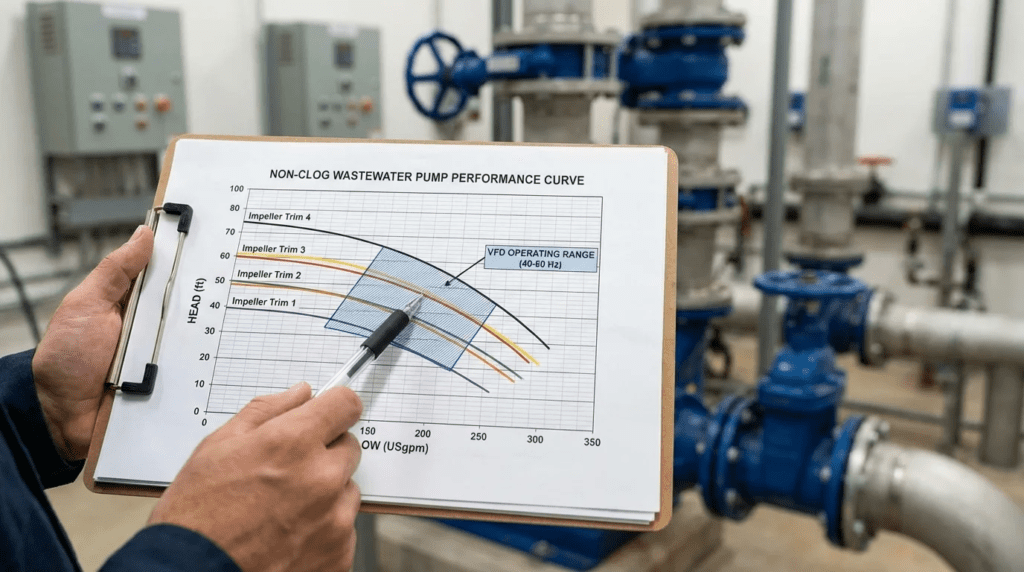
The specification produces a curve; the operator lives on it. Understanding where a pump actually sits relative to its best efficiency point, and what happens as wet well level changes or a force main fouls, is what converts a good specification into good operation. Our operator-focused guide to pump curve reading covers best efficiency point, runout, shutoff head, and how control settings move the operating point across the curve. This material is worth putting in front of operations staff during commissioning rather than leaving in the design file, because the people adjusting level settings and responding to alarms are the ones determining where the pump spends its service life.
How to Select / Specify
Developing a robust specification requires a holistic view of the lift station. The following criteria form the backbone of a defensible and effective Selection Guide: How to Specify Non-Clog Wastewater Pumps for Municipal Lift Stations.
Duty Conditions & Operating Envelope
The foundation of pump selection is the accurate definition of the operating envelope. In wastewater applications, a single duty point is rarely sufficient due to diurnal flow variations and changing static head levels in the wet well.
- System Curve Generation: Engineers must calculate the system curve across the full range of operation (pump off level to lead pump on level). This defines the minimum and maximum static head. Intersection with the pump curve must occur within the pump’s Preferred Operating Region (POR), typically between 70% and 120% of the Best Efficiency Point (BEP).
- Variable Frequency Drives (VFDs): If VFDs are utilized to match influent flow, the specification must analyze the pump’s performance at minimum speed. Ensure that the discharge velocity remains above scouring velocity (typically 2.0 to 3.0 ft/sec) even at the lowest operating speed to prevent solids deposition in the force main.
- NPSH Margin: Net Positive Suction Head Available (NPSHa) must exceed NPSH Required (NPSHr) by a safety margin, typically 3 to 5 feet, to prevent cavitation. This is critical in dry-pit applications or shallow wet wells where submergence is limited.
Materials & Compatibility
Standard gray cast iron (ASTM A48 Class 30 or 35B) is the industry baseline for volutes and generic components. However, specific environmental factors often dictate upgraded metallurgy.
- Abrasion Resistance: For lift stations serving combined sewers or areas with high grit/sand content, standard cast iron impellers will erode quickly. Specifying High Chrome Iron (ASTM A532) or hardened stainless steel for the impeller and wear plate can extend component life by 300-500%.
- Corrosion Resistance: In septic environments with high H2S concentrations, corrosion is a primary failure mode. While CD4MCu (Duplex Stainless Steel) offers excellent chemical resistance, it is a significant cost adder. For many municipal applications, a high-solids epoxy coating on the exterior and standard materials internally is a cost-effective compromise, unless industrial chemical influencers are present.
- Shaft Material: Specify 400-series stainless steel as a minimum for strength, or 300-series for superior corrosion resistance, ensuring the shaft is sized to minimize deflection at the seal face (typically < 0.002 inches).
Hydraulics & Process Performance
The core conflict in wastewater pump selection is the trade-off between hydraulic efficiency and solids handling capability. The selection of the impeller type is the most critical decision in this guide.
- Solids Passage: The traditional “3-inch spherical solids capacity” standard is no longer the only metric for success. While a pump may pass a hard sphere, it may easily rag on fibrous wipes. Modern specifications should prioritize “rag handling” or “fibrous material handling” capabilities over pure sphere size for sanitary sewer applications.
- Steep vs. Flat Curves: For lift stations discharging into a common force main (manifold system), steep head-capacity curves are preferred. They minimize flow variations caused by pressure fluctuations in the main when other stations cycle on/off.
- Wire-to-Water Efficiency: While high efficiency is desirable, it should not compromise reliability. An enclosed channel impeller may offer 80% efficiency but clog weekly. A vortex impeller may offer 55% efficiency but never clog. The cost of one service call often exceeds a year’s worth of energy savings from efficiency differences.
Installation Environment & Constructability
The physical constraints of the lift station dictate the pump configuration. The specification must align with the civil and structural reality.
- Submersible (Wet Pit): The most common configuration for municipal lift stations. Critical specification points include the guide rail system (stainless steel vs. galvanized), the discharge base elbow design (metal-to-metal contact vs. O-ring seals), and cable management systems to prevent cable damage during pull-up.
- Dry Pit Submersible: This hybrid approach places a submersible motor pump in a dry vault. It offers the flood protection of a submersible with the ease of maintenance of a dry pit. Engineers must specify cooling jackets or ensuring the motor is rated for continuous in-air operation without external cooling water.
- Immersible: Distinct from submersible, immersible motors are standard TEFC motors with special sealing to withstand temporary flooding (e.g., 30 feet for 2 weeks). These are often used in dry pit applications where full submergence capability is required for redundancy.
Reliability, Redundancy & Failure Modes
Reliability must be engineered into the specification through robust component choices and redundancy strategies.
- Bearing Life: Specify an L10 bearing life of minimum 50,000 hours (some utilities require 100,000 hours) at the Best Efficiency Point. Bearings should be permanently lubricated or oil-bath lubricated.
- Mechanical Seals: Dual mechanical seals in a tandem arrangement are the industry standard. The inner seal (impeller side) should be Silicon Carbide vs. Silicon Carbide (or Tungsten Carbide) to resist abrasion. The outer seal (motor side) can be Carbon vs. Ceramic.
- Moisture & Thermal Protection: The pump must include moisture detection probes in the oil chamber (to detect seal failure) and the stator housing. Thermal switches embedded in the stator windings are mandatory to protect against overload and phase failure.
Controls & Automation Interfaces
Modern non-clog pumps are part of an integrated system. The specification must address how the pump interacts with the SCADA and local control panel.
- De-Ragging Functionality: If VFDs are used, specify a “cleaning cycle” or “anti-ragging” algorithm. This feature detects torque spikes associated with incipient clogging and briefly reverses the pump or ramps speed to clear the obstruction without operator intervention.
- Condition Monitoring: For critical stations (larger than 5 MGD or high consequence of failure), specify vibration sensors and bearing temperature monitors integrated into the pump housing, with outputs compatible with the plant SCADA system.
Lifecycle Cost Drivers
A rigorous Selection Guide: How to Specify Non-Clog Wastewater Pumps for Municipal Lift Stations must consider Total Cost of Ownership (TCO), not just the bid price.
TCO Calculation = CAPEX + (Energy Cost × Years) + (Maintenance Cost × Years) + (Downtime Cost)
Maintenance labor is often the highest variable. A pump that requires monthly de-ragging (2 technicians, 4 hours, truck roll) can cost a utility $15,000+ annually in O&M, dwarfing a $2,000 savings in initial purchase price or a 2% gain in hydraulic efficiency.
Comparison Tables
The following tables provide a comparative analysis to assist engineers in selecting the correct impeller geometry and installation type. These tables highlight the trade-offs between efficiency, solids handling, and application suitability, serving as a quick reference within this Selection Guide: How to Specify Non-Clog Wastewater Pumps for Municipal Lift Stations.
Table 1: Impeller Technology Comparison
| Impeller Type | Hydraulic Efficiency (Typical) | Solids Handling Character | Best-Fit Application | Limitations / Considerations |
|---|---|---|---|---|
| Enclosed Channel (Single/Multi-Vane) | High (75% – 85%) | Good for spheres; Poor for rags. | High-flow, continuous duty, screened influent, or stormwater. | Tight clearances between wear rings make this prone to binding with stringy materials/wipes. Requires regular clearance adjustment. |
| Semi-Open / Back-Swept | Medium-High (70% – 80%) | Excellent for rags; Good for grit. | Raw sewage with high wipe content; Lift stations with variable flow. | Requires a serrated suction cover or groove to shred solids effectively. Maintainability depends on wear plate adjustment. |
| Vortex (Recessed) | Low (40% – 60%) | Superior. Creates flow without contacting most solids. | Low-flow, high-solids applications; Sludge pumping; Gritty influent. | Low hydraulic efficiency increases energy costs significantly. Not suitable for high-head applications. |
| Chopper / Cutter | Medium (60% – 75%) | Aggressive. Actively reduces solid size. | Problem stations with history of chronic clogging; Institutions (prisons, hospitals). | Higher maintenance cost to sharpen/replace cutter bars. Can be overkill for standard residential lift stations. |
| Screw / Centrifugal-Screw | High (70% – 80%) | Excellent handling of thick sludge and rags. Gentle handling. | RAS/WAS pumping; Influent with high fibrous content. | Often physically larger pumps. Can be expensive compared to standard centrifugal options. |
Table 2: Application Fit Matrix
| Scenario | Recommended Configuration | Key Constraint / Driver | Critical Spec Feature |
|---|---|---|---|
| Small Subdivision Lift Station (< 100 GPM) | Submersible / Vortex or Grinder | Low flow velocities lead to clogging; Limited maintenance budget. | Specify steep curve to prevent dead-heading; Hardened components if grinder is used. |
| Regional Lift Station (High Wipes/Ragging) | Submersible / Chopper or Semi-Open | Must eliminate weekly de-ragging trips. Reliability is paramount. | Hard iron material (ASTM A532); Cutter elements or relief groove on suction plate. |
| Master Lift Station (> 5 MGD) | Dry Pit (Coupled or Submersible) / Enclosed Channel | Energy efficiency dominates lifecycle cost due to scale. | Tight efficiency spec (premium efficiency motors); Vibration monitoring; Ease of access for maintenance. |
| Deep Tunnel / High Head Application | Submersible / Multi-Stage or High-Head Channel | High static head requirements (TDH > 150 ft). | Heavy-duty shaft and bearing assembly to handle radial loads; Check NPSHr carefully. |
Engineer & Operator Field Notes
Specification is theory; operation is reality. This section incorporates lessons learned from the field to strengthen the design process.
Commissioning & Acceptance Testing
A rigorous acceptance protocol is the first line of defense against premature failure.
- Vibration Baseline: Do not accept a pump without a baseline vibration signature taken in situ (not just at the factory). Compare against ISO 10816 standards for Zone B/C machines. High vibration at startup often indicates resonance issues with the rail system or piping, not necessarily the pump itself.
- Draw-Down Test: Verify volumetric performance by isolating the wet well and timing the draw-down between two known levels. This confirms the installed capacity matches the curve, accounting for actual friction losses which often differ from theoretical calculations.
- Amperage Check: Verify amp draw across all three phases. Imbalance greater than 5% suggests power supply issues or motor winding defects.
Common Specification Mistakes
- Oversizing the Pump: Engineers often add safety factors to the friction loss, then to the static head, and finally select a pump “to the right” of the design point. This forces the pump to operate far to the left of its curve during actual operation (high head, low flow), leading to recirculation cavitation, high radial loads, and premature seal failure.
- Ignoring Minimum Flow: Failing to specify a minimum continuous stable flow (MCSF) leads to pumps running in thermal danger zones. Ensure the control logic prevents operation below this threshold.
- Vague Material Specs: Simply saying “Cast Iron” allows for lower grade materials. Specify ASTM A48 Class 35B minimum to ensure structural integrity and better vibration damping.
O&M Burden & Strategy
The design must facilitate maintenance. If a pump is hard to service, it won’t be serviced.
- Access Hatch Sizing: Hatches must be large enough to pull the pump and allow a technician to see the guide rails during seating. Undersized hatches result in damaged seals during installation.
- Lifting Equipment: Specify permanent lifting davits or cranes for pumps exceeding 100 lbs. Reliance on operator back-strength or portable tripod availability is a safety violation risk.
- Oil Change Intervals: Standard intervals are 2,000 to 4,000 hours. Specify ports that allow oil changes without full disassembly of the pump.
Diagnosing a Station That Keeps Clogging
When a station moves from occasional to routine intervention, resist the temptation to treat it as a pump defect until the alternatives are eliminated. Work the diagnosis in this order.
- Characterize the blockage. Photograph and describe what comes out during de-ragging. A rope of textile fibres, a grease mat, and a grit accumulation each indicate a different corrective path, and the record matters when specifying the replacement.
- Check the wet well before the pump. Solids that settle during low-flow periods and re-suspend as a mass when the pump starts will clog even a well-chosen impeller. Look at benching, floor slope, inlet drop, and whether the pump-off level leaves standing solids behind.
- Verify the operating point. A pump running far left of best efficiency during most of its cycle sees recirculation at the impeller eye, which encourages material to accumulate rather than pass. Confirm where the duty point actually sits before concluding the geometry is at fault.
- Review cycle frequency and run time. Very short run times prevent the force main from reaching scouring velocity and allow deposition that eventually returns as a slug. Longer, less frequent cycles often reduce clogging without any hardware change.
- Only then change the pump. If the influent genuinely exceeds what the installed geometry can pass, move to a semi-open back-swept, vortex, or chopper configuration according to what the blockage characterization showed.
Design Details / Calculations
Precision in calculation prevents costly retrofits. This section details the sizing logic required for this Selection Guide: How to Specify Non-Clog Wastewater Pumps for Municipal Lift Stations.
Sizing Logic & Methodology
- Define Static Head: Calculate the vertical distance from the “Pump Off” level in the wet well to the highest point of the discharge piping.
- Calculate Friction Loss (Hf): Use the Hazen-Williams equation. For wastewater, use a C-factor of 100 to 120 (conservative) for old pipe, and 130-140 for new PVC/HDPE.
Equation: Hf = 0.2083 × (100/C)1.85 × q1.85 / d4.8655 (per 100 ft) - System Curve Construction: Plot Total Dynamic Head (Static + Friction) at various flow rates.
- Intersection Analysis: Overlay the pump performance curve. The operating point is the intersection.
- Check operation with one pump running (Design Point).
- Check operation with two (or more) pumps running in parallel (Modified System Curve). The combined flow will not be double the single pump flow due to increased friction losses.
Working the System Curve Envelope
A single system curve is not enough for a lift station, because two variables move underneath it. Static head changes continuously as the wet well draws down between the lead-on and pump-off levels, and friction loss grows over the years as the force main ages and its effective C-factor declines. The result is an envelope rather than a line, and the pump must remain inside its preferred operating region across all four corners of that envelope: high level with a clean main, low level with a clean main, high level with an aged main, and low level with an aged main.
The practical consequence is that a pump selected precisely at the design point on a new-pipe curve will drift left as the main fouls and right as the well draws down, and the two effects do not cancel. Check the extremes explicitly. For parallel operation, plot the combined curve as well: two pumps running together on a force main sized for one will each deliver considerably less than their individual rated flow, and the operating point moves left on each pump’s curve, which is exactly the region where recirculation and radial loading shorten seal and bearing life.
Specification Checklist
Before issuing a bid package, verify these items are explicitly defined:
- Performance Standard: Hydraulic Institute (HI) Grade 1B or 2B testing tolerance.
- Motor Rating: Service Factor (typically 1.15), Insulation Class (F or H), and Temperature Rise (Class B).
- Seal Failure Relay: Must be included in the control panel supply or specified as compatible with existing controls.
- Coating: Dry film thickness (DFT) and surface prep (e.g., SSPC-SP10 Near White Metal Blast) for submerged components.
- Warranty: Standard is 1 year; consider specifying a 5-year pro-rated warranty for municipal applications.
- Minimum Submergence: State the required submergence at pump-off level and require the supplier to confirm it against their intake geometry, rather than leaving it to the civil drawings alone.
- Minimum VFD Speed: Define the lowest permitted operating speed based on both scouring velocity in the force main and motor cooling, and require the drive parameters to enforce it.
- Solids Handling Demonstration: For stations with a ragging history, require a witnessed demonstration passing a defined test article rather than accepting a sphere-size rating alone.
Standards & Compliance
Adherence to industry standards protects the engineer from liability and ensures quality.
- HI 1.1-1.2 & 1.3: Rotodynamic Centrifugal Pumps for Nomenclature and Applications.
- HI 11.6: Rotodynamic Submersible Pumps for Hydraulic Performance, Hydrostatic Pressure, Mechanical, and Electrical Acceptance Tests.
- HI 9.8: Rotodynamic Pumps for Pump Intake Design — the governing reference for wet well geometry, approach flow, and submergence.
- AWWA: While AWWA focuses largely on potable water, general equipment standards often apply.
- NEC (NFPA 70): specifically Article 500/501 for Class 1, Division 1 or 2 hazardous locations (Explosion Proof requirements).
- NEMA MG1 Part 31: Inverter duty motor requirements, applicable wherever a VFD is specified.
HI 9.8 is the standard most often skipped on small and mid-size lift stations, and its omission produces failures that get attributed to the pump. Intake design governs approach velocity, floor and wall clearances, and the submergence required to suppress free-surface and submerged vortices. A pump meeting every performance guarantee in HI 11.6 will still draw air, lose head, and vibrate if the basin around it does not meet HI 9.8. Cite both in the specification, and require the supplier to review the wet well drawings rather than only the duty point.
FAQ Section
What defines a “non-clog” wastewater pump?
A non-clog pump is defined by its hydraulic geometry designed to pass solids without jamming. Historically, this meant the ability to pass a 3-inch spherical solid. However, modern definitions focus on the ability to handle stringy fibrous materials (rags/wipes) through features like semi-open back-swept impellers, chopper blades, or vortex designs that minimize contact between the solid and the impeller vanes.
How do I choose between a grinder pump and a non-clog solids handling pump?
Grinder pumps are typically used for low-flow, high-head applications (e.g., individual home pressure sewers or very small lift stations < 50 GPM) where piping is small diameter (1.25″ – 2″). Non-clog solids handling pumps are preferred for larger municipal lift stations (> 50-100 GPM) utilizing 4″ or larger force mains, as they are generally more efficient, durable, and less prone to mechanical jamming than grinders in high-volume applications.
What is the typical lifespan of a submersible wastewater pump?
In municipal applications, a quality submersible non-clog pump typically has a service life of 15-20 years. However, “wet end” components (impellers, wear plates, mechanical seals) generally require rehabilitation or replacement every 5-7 years depending on grit load and cavitation. Motors often outlast the hydraulics if moisture is kept out and thermal overloads are prevented.
How does a VFD impact the selection of a non-clog pump?
VFDs allow pumps to match influent flow, reducing cycling and energy usage. However, when specifying VFDs, engineers must ensure the motor is “inverter duty” rated (MG1 Part 31). Furthermore, the pump must be selected so that at minimum speed, it still generates enough head to overcome static pressure and enough flow to maintain scouring velocity (typically 2 fps) in the force main to prevent solids settling.
What is the difference between suction lift and flooded suction in pump specifications?
Flooded suction (submersible or dry pit with positive pressure) means gravity feeds the fluid into the pump eye. Suction lift (self-priming pumps mounted above the wet well) requires the pump to create a vacuum to pull water up. Flooded suction is generally preferred for reliability in lift stations as it eliminates priming failures, though self-primers offer easier access for maintenance since they are not submerged.
Why is the Best Efficiency Point (BEP) critical in Selection Guide: How to Specify Non-Clog Wastewater Pumps for Municipal Lift Stations?
Running a pump at its BEP minimizes radial forces on the shaft and bearings. Operating too far left of BEP causes recirculation cavitation and high vibration; operating too far right causes potential cavitation and motor overload. Specifying a pump where the duty point falls within 70-120% of BEP ensures maximum component life and reliability.
When should I specify a chopper pump over a standard non-clog pump?
Chopper pumps should be specified for “problem” lift stations that experience chronic clogging (e.g., weekly operator intervention required) due to high concentrations of wipes, hair, or institutional waste (prisons/hospitals). While they may have slightly lower hydraulic efficiency and higher maintenance costs for cutter bars, the elimination of emergency unclogging labor justifies the selection in severe environments.
How much submergence does a submersible pump actually need?
Enough to prevent air-entraining vortices from forming above the intake, which depends on intake velocity and geometry rather than on a single universal figure. Higher approach velocity and larger intakes require more submergence, and HI 9.8 provides the methodology for calculating it. Insufficient submergence produces symptoms that mimic mechanical faults: reduced head, fluctuating amp draw, noise, and vibration, with accelerated bearing and seal wear. Because pump-off level is usually set to maximize working volume, this is a common place for a well-specified pump to be undermined by the basin design around it. Establish the submergence requirement before fixing control levels.
Should lift station pumps run at constant speed or on a VFD?
It depends on flow variability and force main hydraulics. Constant speed is simpler, cheaper, and entirely adequate where diurnal variation is modest and the station can cycle without excessive starts. VFDs earn their cost where influent varies widely, where soft starting reduces surge in a long force main, where cycling frequency would otherwise exceed motor start limits, or where a de-ragging routine is valuable. The trade-offs are real: reduced speed means reduced motor cooling on a submersible, harmonics add heat, and operating below scouring velocity allows solids to deposit in the main. If a VFD is specified, the minimum speed limit should be set by whichever of those constraints binds first, and it should be enforced in the drive parameters rather than left to operator discretion.
Why do two pumps running in parallel not deliver twice the flow?
Because friction loss in the force main rises roughly with the square of flow. When the second pump starts, the combined flow increases, which raises system head, which pushes both pumps left along their curves to a lower flow each. On a force main sized around single-pump operation, two pumps together may deliver only 120 to 150 percent of single-pump flow rather than 200 percent. This matters for firm capacity calculations and for component life, since both pumps are now operating further from best efficiency than either does alone.
Conclusion
Key Takeaways
- Define the Fluid: Do not treat modern wastewater as clear water. Account for rags, wipes, and grit by prioritizing impeller geometry (vortex, semi-open, or chopper) over pure hydraulic efficiency.
- Calculate the System Curve: Accurate head calculations are vital. Ensure the pump operates within the Preferred Operating Region (70-120% of BEP) to maximize bearing and seal life.
- Material Matters: Specify Hard Iron (ASTM A532) for grit environments and ensure proper motor cooling for dry pit applications.
- Minimum Velocity: When using VFDs, ensure the discharge velocity never drops below 2 ft/sec to prevent force main sedimentation.
- TCO Focus: Maintenance labor for de-ragging usually exceeds energy costs. A slightly less efficient pump that never clogs is the superior engineering choice.
- The Wet Well Is Part of the Pump: Intake geometry and minimum submergence determine whether the specified hydraulics are ever achieved, and basin defects routinely present as pump faults.
The process outlined in this Selection Guide: How to Specify Non-Clog Wastewater Pumps for Municipal Lift Stations is designed to move engineers from simple catalog selection to comprehensive system design. The successful lift station is not just about the pump; it is about the integration of hydraulic performance, material science, and control logic.
By shifting the focus from initial bid price to lifecycle reliability, municipal engineers can deliver infrastructure that withstands the challenging reality of modern wastewater composition. When in doubt, consult with application specialists to review system curves and conduct solids-handling demonstrations. The subcategory guides linked above cover manufacturer selection, wet well design, VFD configuration, and curve interpretation in the depth each of those decisions warrants. The goal is a system that runs silently in the background, keeping the “3:00 AM alarm” a rarity rather than a routine.