
Singer Valve vs AVK Ball Valves Equipment: Comparison & Best Fit
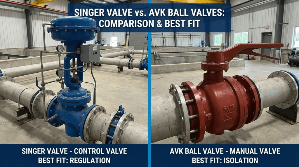
Singer Valve vs AVK: Control Valves and Isolation Valves Compared
Introduction
The choice between a hydraulically pilot-operated control valve and a mechanically actuated rotary valve is one of the more consequential decisions in pump station and distribution design, and it is frequently made on habit rather than hydraulics. Singer Valve, a Mueller brand, builds diaphragm-actuated automatic control valves that use line pressure to modulate position. AVK builds mechanical isolation valves operated by gearbox or actuator.
These are different hydraulic philosophies, and they overlap in a narrow band: pump control valves and reservoir management. Outside that band they diverge sharply. A control valve asked to serve as a low-loss isolation valve wastes pumping energy for decades; an isolation valve asked to regulate pressure cavitates and wire-draws its seat.
Manufacturer positioning across the wider category is covered in our overview of the top OEMs for ball valves.
How to Select and Specify
Duty Conditions and Operating Envelope
- Head loss: Where minimising pumping cost is the governing constraint, a full-port rotary valve is superior. A globe-pattern control valve forces flow through a tortuous path and retains a permanent pressure drop even at full open. Over a twenty-year asset life on a high-flow main, that parasitic loss is a substantial operating cost.
- Modulation versus isolation: Where the requirement is holding a downstream pressure against a varying inlet, an automatic control valve with a pressure-reducing pilot is the correct technology. Rotary valves have non-linear flow characteristics and high recovery factors, making precise throttling difficult without V-port trim and high-resolution actuation.
- Minimum differential: Pilot-operated valves need a minimum differential pressure to drive the diaphragm reliably. In very low head applications they may not open fully or close tightly without assistance.
Materials and Compatibility
- Control valves: Typically ductile iron bodies with epoxy coating, stainless seats and stems, and elastomeric diaphragms. The vulnerability is the pilot system — small-bore tubing, orifices and strainers that clog when solids are present.
- Rotary isolation valves: Also ductile iron with epoxy or polyurethane coatings. Wear concentrates at bearings and seat rings rather than in small passages, which is why they tolerate dirty fluids better.
Hydraulics and Process Performance
- Cavitation: Control valves are available with anti-cavitation trim that breaks pressure differential down in stages, making them the correct choice for high pressure-drop duty such as filling a reservoir from a high-pressure zone. Rotary valves throttling across a large differential suffer cavitation damage on the trailing edge of the closure element and on the seat.
- Surge: Pilot-operated surge anticipation valves respond directly and rapidly to pressure change. Actuated rotary valves mitigate surge through controlled slow closure, which depends on the actuator having power or stored energy when the pump trips. The right choice depends on whether the system needs to relieve a pressure spike or to prevent column separation through timed closure.
Installation and Power
- Power dependency: A pilot-operated valve is hydraulically powered and functions without electricity unless solenoids are added for SCADA control. An actuated rotary valve requires reliable power; without backup, a standard electric actuator becomes a manual valve during an outage and loses any check function it was providing.
- Footprint: Control valves need vertical clearance for bonnet and pilot removal. Actuators add bulk to the side or top of the valve. Both constraints are best modelled before the vault or gallery is poured.
Failure Modes
- Control valves: Diaphragm rupture or pilot clogging. The pilot system behaves like a hydraulic circuit — a failure in one small sensing line disables the whole valve. Fail-open, fail-closed or hold-position behaviour depends on the pilot schematic and should be specified explicitly.
- Rotary valves: Mechanically simpler, but dependent on actuator and gearbox reliability. A stalled electric actuator leaves the valve in its last position.
Comparison
| Criterion | Pilot-operated control valve | Actuated rotary valve |
|---|---|---|
| Mechanism | Hydraulic pilot acting on a flexible diaphragm in a globe or angle body | Quarter-turn rotation of ball or disc driven by actuator or gearbox |
| Throttling | Excellent; anti-cavitation trim available | Poor to fair; non-linear, high gain near closure |
| Head loss open | Moderate to high | Negligible with full-bore designs |
| Power required | None; operates on line pressure | Electric, pneumatic or hydraulic actuation needed |
| Solids tolerance | Limited; pilot circuit clogs | Good; full port passes solids |
| Pressure management | Primary function | Not applicable |
| Maintenance | Frequent but low cost — strainers, diaphragms | Infrequent but high cost when seats or bearings fail |
| Application | Better fit | Rationale |
|---|---|---|
| District pressure reducing station | Control valve | Holds downstream pressure regardless of demand |
| Raw water pump discharge | Actuated rotary valve | Low head loss; tolerates solids; timed closure for surge |
| Transmission main isolation | Actuated rotary valve | Tight shutoff, negligible drop, reliable infrequent operation |
| Surge relief and anticipation | Control valve | Hydraulic pilots respond faster than mechanical actuation |
| Reservoir altitude control | Control valve | Hydraulic level sensing without external power or wiring |
| Remote site, no power | Control valve | Self-powered from line pressure |
Field Notes
Commissioning
Control valves: The critical step is bleeding air from the bonnet. Trapped air is compressible and produces hunting — rapid oscillation — or sluggish response. Pilot setpoints must be verified during site acceptance, and speed-of-control needle valves set conservatively; set too fast, the valve slams.
Actuated rotary valves: Commissioning centres on actuator limits. Open and closed positions must be set precisely, because an electric actuator driving into a mechanical stop can shear the stem or damage the gearbox. For pump control, opening and closing times should be timed against the surge analysis rather than assumed.
Specification Mistakes
Oversizing is the most frequent error with control valves. Engineers match valve size to line size, but a control valve needs meaningful lift to operate stably. An oversized valve runs cracked open near the seat, causing wire drawing and instability. Specifying a control valve one size below line diameter is common and correct.
For actuated valves the equivalent error is undersizing the actuator. Break-away torque after months of inactivity substantially exceeds running torque. Specifications should require a safety factor of at least 1.5 on the valve’s maximum break torque.
Maintenance
Control valves:
- Monthly: inspect pilot fittings for external leaks
- Quarterly: clean the pilot line strainer — the single most common cause of failure
- Multi-year: replace main diaphragm and seat disc; a confined space task in vaulted installations
Actuated rotary valves:
- Semi-annually: partial-stroke cycle to prevent seal adhesion and verify actuator function
- Annually: check gearbox oil and grease bearings where accessible
- Long term: seat replacement on large valves generally requires removal from the line
Design Details
Sizing a Control Valve
Sizing is based on flow coefficient and allowable pressure drop: ΔP = SG × (Q / Cv)², where Q is flow in gpm and SG is specific gravity.
- Calculate valve position at minimum, average and peak flow
- Target roughly 20 to 30 percent open at minimum flow and no more than 80 to 90 percent at peak
- Check the cavitation index; where it falls below the manufacturer’s threshold, specify anti-cavitation trim
Sizing an Actuated Rotary Valve
- Keep line velocity within the manufacturer’s rating
- Obtain seating and unseating torque from the valve manufacturer and apply the actuator safety factor to those figures
- Verify actuator stroking time meets the closure time the surge analysis requires; rapid closure of a large valve generates severe water hammer
Standards
- AWWA C530: Pilot-operated control valves
- AWWA C507: Ball valves, 6 in. through 60 in.
- NSF/ANSI 61 and 372: Required for potable water service
- Enclosure ratings: Specify appropriately for damp or floodable vaults
Frequently Asked Questions
What is the core difference between these technologies?
Actuation method and hydraulic profile. A pilot-operated control valve is a diaphragm-actuated globe-pattern valve using line pressure to modulate position, suited to pressure and flow regulation. A rotary isolation valve requires external mechanical force and offers a full-bore opening suited to isolation and low-loss pumping service.
Can a rotary valve perform pressure reducing service?
Technically, with V-port trim and high-resolution actuation, but it is not the right tool. Rotary valves have high recovery factors and non-linear characteristics, and they cavitate readily at the pressure drops typical of a reducing station. A control valve with anti-cavitation trim is the standard engineering answer.
Which has lower lifecycle cost?
It depends entirely on duty. For a valve that sits fully open 99 percent of its life, the rotary valve wins on energy alone. For a pressure reducing station, the control valve wins because it performs the duty reliably without power infrastructure or control programming.
Why is there a strainer ahead of a control valve?
The pilot system uses small tubing and orifices. Debris, rust or grit clogs these passages and causes the valve to stick open or closed. The strainer protects that circuit, and cleaning it is the highest-value routine maintenance task on the valve.
When should a rotary valve be chosen for pump control?
When energy efficiency is a primary driver at high flow and long operating hours, when the fluid carries solids, or when reliable power exists and deep SCADA integration through an electric actuator is wanted.
Conclusion
Key Takeaways
- Energy versus control: Rotary valves for low-loss isolation and pump discharge; control valves where hydraulic precision is the point.
- Power: Control valves work on line pressure alone. Actuated valves need power or stored energy to serve any fail-safe function.
- Sizing: Never line-size a control valve for modulating duty; size down for authority. Rotary isolation valves should match line size.
- Solids: Avoid pilot circuits in raw sewage without clean-water pilot supply and non-clog straining.
- Skills: Pilot troubleshooting is a technician-level mechanical skill; actuator work is electrical. Match the technology to the staff you have.
The decision comes down to the primary hydraulic objective. Where the goal is dissipating energy — reducing pressure, relieving surge — the friction-inducing globe geometry of a control valve is a feature rather than a defect, and it is the standard for hydraulic regulation. Where the goal is conserving energy — isolation, transmission, pump discharge — the unobstructed bore of a rotary valve is the efficient answer.
Most well-designed stations use both: rotary valves for isolation and pump control on the main line, control valves handling pressure management, surge anticipation and reservoir level. Related evaluations appear in our comparisons of Proco and Bray equipment and of Ross Valve and Val-Matic ball valves.