
Strainers Cavitation and Noise: Causes
INTRODUCTION
One of the most common and destructive phenomena operators experience in municipal and industrial pumping systems is the unmistakable sound of gravel passing through the piping. While engineers frequently attribute this acoustic signature to pump issues, the true root cause often lies just upstream. When investigating Strainers Cavitation and Noise: Causes typically track back to improperly sized, heavily fouled, or incorrectly specified filtration equipment on the suction side of the system. Neglecting the hydraulic impact of a simple strainer can lead to catastrophic pump failure, severe pipe vibration, and premature wear of downstream components.
Strainers—whether Y-type, simplex basket, duplex, or automatic self-cleaning units—are indispensable in municipal water treatment, wastewater utilities, and industrial process applications. Their primary function is to protect critical equipment (pumps, heat exchangers, control valves, and flow meters) from rogue debris, pipe scale, and biological fouling. However, introducing a mechanical barrier into a fluid stream inherently creates pressure drop. If this pressure drop is not meticulously managed across the full operating envelope, the strainer becomes a choke point, triggering complex and destructive hydraulic phenomena.
Proper selection and specification of strainers matter immensely. A poor choice can reduce Net Positive Suction Head available (NPSHa) below critical thresholds, leading to suction-side cavitation, severe acoustic noise, and mechanical degradation. By understanding the fluid dynamics at play, engineers can prevent these issues during the design phase. This article provides municipal consulting engineers, plant superintendents, and operators with a comprehensive, technical guide to diagnosing, preventing, and engineering solutions for strainer-induced cavitation and fluid noise.
It also serves as the entry point for the strainer material on this site, covering the equipment family as a whole before going deep on cavitation and noise specifically. Strainers sit within the broader Instrumentation & Controls domain more naturally than their simple appearance suggests: a strainer without differential pressure instrumentation is an unmonitored failure waiting to happen, and the monitoring strategy is as much a part of the specification as the body material. The sections below establish the equipment types and subtopics, then work through selection, hydraulics, field practice, and calculation methodology.
STRAINER TYPES AND SUBTOPIC OVERVIEW
Strainer selection begins with matching the body configuration to the debris load and the operational tolerance for downtime. The four configurations below account for essentially all municipal and industrial installations, and the choice among them determines the cavitation risk profile far more than any downstream adjustment can. This section also covers the manufacturer landscape and the broader equipment context; the same specification logic applied here appears across the site’s guidance on water treatment equipment generally.
Y-Strainers
The Y-strainer is the most widely installed configuration in water and wastewater service, taking its name from the angled branch that holds the screen element. Its appeal is compactness and cost: the body installs inline with no additional footprint, tolerates any orientation, and costs a fraction of a basket strainer at the same line size. The hydraulic cost of that compactness is a small screen area and a correspondingly low Open Area Ratio, which is precisely why Y-strainers dominate the cavitation complaints described later in this article.
The design suits low debris loads and equipment protection duties — upstream of control valves, flow meters, and chemical metering pumps — where the screen is catching occasional scale rather than continuous solids. It is a poor choice for pump suction on a raw or partially treated stream, where the small screen blinds quickly and drives differential pressure into the danger zone within days rather than months. Blowdown valves flush loose debris but do not clean a blinded screen, so a Y-strainer in a fouling service still requires system shutdown for cleaning. Where a Y-strainer is the right answer, specifying a heavier screen gauge and a generous mesh opening buys meaningful margin at almost no cost.
Simplex and Duplex Basket Strainers
Basket strainers move the screen into a vertical chamber with substantially more surface area, raising the Open Area Ratio and flattening the pressure drop curve. A simplex unit holds one basket and requires system isolation to clean it; a duplex unit pairs two chambers with a diverter valve so flow continues on one side while the other is serviced. The duplex arrangement is what makes proactive cleaning possible: operators can switch and clean at a differential pressure setpoint rather than waiting for a shutdown window, which is the single most effective structural defense against strainer-induced cavitation on continuous-duty pump suction.
The trade is capital cost, footprint, and the diverter valve itself, which becomes a maintenance item and a potential leak path. For critical municipal duties — raw water intake, membrane pre-filtration, boiler feed — the duplex configuration is generally the minimum defensible specification regardless of budget pressure, because the alternative is a system that can only be cleaned by being taken offline.
Automatic Self-Cleaning Strainers
Automatic units add motorized scrapers, brushes, or backwash arms triggered by a differential pressure signal, removing the human element from the cleaning cycle entirely. In high-solids service at remote or unmanned stations, this is the only configuration that reliably prevents the slow fouling progression that ends in cavitation, because it responds to the actual hydraulic condition rather than to a maintenance calendar. Wedge wire screen elements are standard here and resist the particle pegging that permanently blinds woven mesh.
The costs are real and should be scoped honestly: highest capital cost in the category, an electromechanical drive with motors and seals that requires its own maintenance program, controls integration work, and a backwash discharge that must go somewhere. Automatic strainers trade a simple mechanical problem for a more complex electromechanical one, which is the right trade at a raw water intake and the wrong one on a clean chemical feed line.
Distribution System Applications
Strainers appear throughout potable distribution as well as inside treatment plants, protecting pressure-reducing stations, altitude valve assemblies, and the solenoid-operated control valves inside automatic flushing units. Devices covered under hydrant equipment commonly integrate a small strainer ahead of the control valve for exactly this reason, since a single piece of pipe scale lodged in a solenoid seat will hold a flushing valve open until someone notices the water. These in-line applications share the same failure logic as plant installations at smaller scale: the strainer is invisible until it fouls, and nothing monitors it.
Manufacturer Selection
Published flow coefficient data, basket burst ratings, and open area figures vary enough between suppliers that they are a legitimate selection criterion rather than boilerplate. A review of the top OEMs for strainers covers the principal suppliers in municipal water and wastewater service and how their product lines differ on body configurations, screen options, materials, and automatic cleaning mechanisms. Manufacturer choice carries more weight than in commodity fittings because screens and baskets are rarely interchangeable across brands, so standardizing a plant on one supplier reduces spare inventory and simplifies the basket rotation strategy described in the field notes below. Regional service coverage matters for automatic units in particular, where a failed drive motor takes the strainer out of automatic operation entirely.
HOW TO SELECT / SPECIFY
Specifying a strainer requires far more than simply matching the flange size to the existing piping. To eliminate the risk of strainer-induced cavitation, engineers must evaluate the complete hydraulic and mechanical operating environment.
Duty Conditions & Operating Envelope
The first step in preventing cavitation is accurately defining the duty conditions. Strainers must be sized based on the maximum anticipated flow rate, not the nominal or average flow. High fluid velocities are the primary catalyst for severe differential pressure (ΔP) drops.
- Flow Rates and Velocities: Liquid velocities through the strainer body should typically be limited to 5 to 8 ft/s (1.5 to 2.4 m/s) for continuous duty. Exceeding these velocities exponentially increases pressure drop and acoustic noise generation.
- Operating Pressures: Low system static pressure combined with high velocity is a recipe for cavitation. The system pressure must remain safely above the fluid’s vapor pressure throughout the entire strainer assembly.
- Fluid Temperature: As fluid temperature rises, its vapor pressure increases. A strainer handling 180°F (82°C) boiler feed water is at a vastly higher risk of cavitation than one handling 50°F (10°C) municipal raw water, even at identical flow rates and pressures.
- Operating Modes: Intermittent, high-flow demand spikes (e.g., fire pump activation or filter backwash sequences) often cause transient cavitation if the strainer is not sized to accommodate these extreme conditions.
Materials & Compatibility
While materials do not directly dictate the hydraulic causes of cavitation, they determine the equipment’s survivability when cavitation occurs. The implosion of vapor bubbles creates micro-jets that blast the strainer internals with localized pressures exceeding 10,000 psi, leading to pitting and material fatigue.
- Body Materials: Cast iron and carbon steel are highly susceptible to cavitation damage. Stainless steel (304/316L) offers better resilience due to its ductility and work-hardening characteristics. For extreme environments, duplex stainless steels or exotic alloys (e.g., Monel, Hastelloy) may be required.
- Screen/Basket Integrity: The mesh or perforated plate is the thinnest component and the most vulnerable to cavitation erosion and pressure differential collapse. Heavy-gauge wire or reinforced perforated plate is recommended in high-velocity applications.
- Chemical Compatibility: Corrosion weakens the metal matrix, vastly accelerating material loss when coupled with cavitation forces (erosion-corrosion). Ensure elastomers (O-rings, gaskets) and metals are fully compatible with the specific wastewater or chemical stream.
Hydraulics & Process Performance
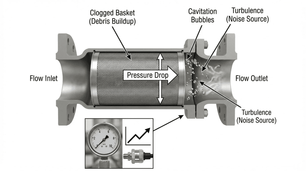
Hydraulic profiling is the core of preventing Strainers Cavitation and Noise: Causes and effects. The physics of cavitation in a strainer are governed by Bernoulli’s principle. As fluid passes through the restricted Open Area Ratio (OAR) of the strainer mesh, its velocity spikes. This kinetic energy increase results in a corresponding localized drop in static pressure.
- Vena Contracta Effect: Just downstream of the mesh orifices, the fluid reaches its maximum velocity and minimum pressure (the vena contracta). If this localized pressure drops below the fluid’s vapor pressure, vapor bubbles form.
- Pressure Recovery and Bubble Collapse: As the fluid exits the basket and expands into the downstream piping, velocity decreases, and pressure recovers. This pressure recovery forces the previously formed vapor bubbles to violently collapse, causing the acoustic noise and mechanical damage associated with cavitation.
- Open Area Ratio (OAR): OAR is the ratio of the total open area of the mesh/perforations to the cross-sectional area of the inlet pipe. A minimum OAR of 3:1 or 4:1 is typically recommended to keep fluid velocities through the screen manageable. Lower OARs rapidly increase the risk of cavitation.
- NPSH Impact: Every PSI of pressure drop across a suction strainer equates to approximately 2.31 feet of lost NPSHa. A dirty strainer can easily consume 5-10 feet of NPSHa, starving the downstream pump.
Installation Environment & Constructability
Improper installation can exacerbate fluid turbulence, increasing the likelihood of noise and localized pressure drops.
- Straight Pipe Runs: To ensure uniform flow distribution across the strainer screen, specify a minimum of 5 to 10 pipe diameters (5D-10D) of straight, unobstructed piping upstream of the strainer. Turbulent, swirling flow from an immediately adjacent elbow or valve will cause localized high-velocity zones within the basket.
- Orientation: Y-strainers in liquid service should typically be installed with the screen pointing downward to trap debris effectively. In horizontal pipelines handling liquids, installing a Y-strainer horizontally can prevent air binding, but the blowdown port must still be positioned to gravity-drain debris.
- Support: Fluid-induced vibration and cavitation shockwaves can fatigue pipe joints. Adequate structural support and pipe hangers near the strainer are essential to mitigate noise transmission.
Reliability, Redundancy & Failure Modes
Strainers are passive devices, but their failure modes are highly disruptive. The most catastrophic failure associated with high differential pressure (often culminating in cavitation) is basket collapse.
- Basket Collapse: When a screen becomes fully blinded, the differential pressure can equal the total system pump dead-head pressure. If the basket is not specified to withstand this ΔP, it will rupture, sending the accumulated debris and the metal screen itself into the downstream pump.
- Redundancy Requirements: For critical, continuous-duty municipal processes (e.g., raw water intake, membrane pre-filtration), Duplex strainers or automatic self-cleaning strainers are mandatory to allow for continuous operation during cleaning cycles.
Controls & Automation Interfaces
Modern wastewater utilities rely on automation to prevent hydraulic failures before they manifest as noise and vibration.
- Differential Pressure (ΔP) Monitoring: This is the single most critical control strategy. A differential pressure transmitter (DPT) should be installed across the strainer. SCADA integration allows for real-time monitoring and alarm generation.
- Alarm Setpoints: A typical clean pressure drop is 1-2 psi. High ΔP alarms are usually set at 5-8 psi, with a high-high critical alarm (pump shutdown or auto-backwash initiation) at 10-15 psi depending on the structural limit of the basket and the pump’s NPSHr.
The value of that differential pressure point depends entirely on what happens to it downstream. A transmitter feeding a local gauge nobody reads delivers nothing; the same transmitter trended in a SCADA system turns a slow fouling curve into a visible, actionable maintenance signal weeks before the acoustic symptoms appear. Historian trending is what separates data-driven cleaning from calendar-driven cleaning, and it is the reason strainers belong in the instrumentation conversation rather than being treated as passive pipe fittings.
Maintainability, Safety & Access
If a strainer is difficult to clean, it won’t be cleaned. An unmaintained strainer is guaranteed to cause cavitation eventually.
- Ergonomics: Large basket strainers require davit arms or lifting lugs to remove heavy, debris-filled baskets safely. Consider the overhead clearance required for extraction.
- Blowdown Valves: Specify quick-opening ball valves on strainer blowdown connections to allow operators to flush loose debris without taking the system offline.
- Isolation: Proper isolation valves and double block-and-bleed setups may be required for safe maintenance in high-pressure or chemically aggressive environments.
Lifecycle Cost Drivers
Evaluating the true cost of a strainer requires balancing capital expenditure (CAPEX) against operating expenditure (OPEX) and risk mitigation.
- Energy Consumption: A smaller, cheaper strainer body operates with a continuously higher baseline pressure drop. In a high-flow municipal pumping system, the energy wasted overcoming an unnecessary 3 psi of constant pressure drop can cost tens of thousands of dollars in electricity over a decade. Sizing up one pipe size often yields an ROI of less than two years in energy savings alone.
- Maintenance Labor: Simplex strainers in high-debris loads require constant manual labor. Upgrading to an automated self-cleaning strainer increases CAPEX significantly but slashes O&M labor and eliminates the risk of human error leading to cavitation.
The most common specification error is automatically matching the strainer connection size to the existing pipe size without calculating the Cv and fluid velocity. If a pipe is undersized, placing a line-size strainer in it will create severe restriction. Always size the strainer for the required flow capacity and allowable pressure drop, even if it requires installing eccentric reducers to step up to a larger strainer body.
COMPARISON TABLES
The following tables provide an objective framework for engineers to evaluate different strainer technologies and application fits. Use these matrices to balance the risk of cavitation, process continuous flow requirements, and lifecycle costs.
| Strainer Type | Features / Hydraulics | Cavitation/Noise Risk | Best-Fit Applications | Maintenance & O&M |
|---|---|---|---|---|
| Y-Strainer | Compact, inline design. Lower Open Area Ratio (OAR). Higher inherent pressure drop. | High if poorly maintained. Small screen area blinds quickly, leading to rapid ΔP spikes. | Clean liquids, steam, gases. Equipment protection where debris load is very low (e.g., upstream of control valves). | Requires system shutdown to clean screen. Blowdown valve can flush loose debris only. |
| Simplex Basket | Large body volume, high OAR. Flat pressure drop curve when clean. | Moderate. High debris holding capacity delays ΔP spikes, but manual cleaning is still required. | Cooling water, batch processes, pump suction where system can be isolated for cleaning. | System must be shut down. Basket removal requires operator lifting (davit required for sizes >8″). |
| Duplex Basket | Two simplex baskets linked by a diverter valve. Uninterrupted flow. | Low. Flow can be diverted to clean basket before critical ΔP is reached, preventing cavitation. | Continuous duty, critical pump suction, fuel oil, cooling towers. | Manual cleaning required, but process remains online. Higher CAPEX. |
| Auto-Cleaning | Motorized scrapers or backwash arms. Driven by ΔP sensors. | Very Low. System automatically cleans before ΔP induces cavitation. | Raw water intake, high TSS wastewater, remote unmanned utility stations. | Low daily labor, but complex electromechanical maintenance (motors, seals, controls). Highest CAPEX. |
| Application Scenario | Primary Constraints | NPSH Criticality | Recommended Technology | Design Mandates |
|---|---|---|---|---|
| Boiler Feed Pump Suction | High fluid temperature, minimal margin to vapor pressure. | Extreme | Oversized Simplex or Duplex Basket | Max clean ΔP < 0.5 psi. Continuous DPT monitoring mandatory. |
| Raw Municipal Intake | High, variable debris load (leaves, organics, plastics). | Moderate to High | Automatic Self-Cleaning | Wedge wire screen (resists blinding). PLC integration for automated backwash. |
| Chemical Feed / Dosing | Corrosion risk, low flow, small pipe diameters. | Low | Y-Strainer (Alloy/PVC) | Verify material compatibility. Mesh size must protect metering pump checks. |
| Secondary Effluent | Constant flow, moderate biological fouling. | Moderate | Duplex Basket | Routine cleaning schedule based on historical biological growth rates. |
ENGINEER & OPERATOR FIELD NOTES
Theoretical sizing only goes so far. Real-world mitigation of noise and cavitation relies on rigorous commissioning, avoiding common specification traps, and executing proactive maintenance.
Commissioning & Acceptance Testing
Proper commissioning establishes the baseline metrics necessary for long-term troubleshooting.
- Baseline ΔP Logging: During the Site Acceptance Test (SAT), document the differential pressure across the strainer at varying flow rates with a perfectly clean basket. This clean baseline curve is vital. If future “clean” readings are higher than the baseline, the mesh is suffering from permanent scaling or embedded particulate.
- Acoustic and Vibration Baselines: Run the system at full design flow. Utilize ultrasonic acoustic monitoring or vibration pens on the downstream pipe to record baseline flow noise. Cavitation generates a distinct high-frequency acoustic signature (broadband noise, typically above 20 kHz) before it becomes audible to the human ear as “gravel.”
- Simulation of Fouling: If permitted by system design, partially throttle a downstream valve to simulate high system pressure, then monitor the suction ΔP to ensure alarms and interlocks activate at the correct setpoints without inducing pump cavitation.
Common Specification Mistakes
When analyzing Strainers Cavitation and Noise: Causes in the field, consulting engineers often discover the root issue was baked into the original bid documents.
- Over-specifying Mesh Size: Specifying a 100-mesh (149 micron) screen for a pump that can comfortably pass 0.5-inch solids is a critical error. Over-filtration drastically reduces the OAR, accelerates blinding, and guarantees a rapid onset of high ΔP and cavitation. Rule of thumb: Size the mesh perforations to be approximately one-half the diameter of the largest solid the downstream equipment can safely pass.
- Ignoring Fluid Viscosity: Standard Cv values and pressure drop charts published by manufacturers are based on water at 60°F. If specifying a strainer for primary sludge or polymer, engineers must apply viscosity correction factors. Failing to do so will result in massively undersized strainers.
- Missing Structural Specs: Failing to specify the “Maximum Allowable Differential Pressure” (MADP) for the basket. A standard basket might collapse at 15 psi ΔP; reinforced baskets can withstand 50+ psi.
O&M Burden & Strategy
Preventive maintenance is the primary defense against strainer-induced hydraulic failures.
- Data-Driven Cleaning: Do not rely on fixed-time intervals (e.g., “clean the strainer every Tuesday”) unless flow and debris loads are perfectly constant. Establish cleaning protocols based solely on ΔP transmitter data. Clean the basket when the ΔP reaches 50% of the maximum allowable limit.
- Basket Rotation: For critical simplex strainers, maintain a clean, spare basket adjacent to the installation. Operators should swap the dirty basket with the clean one immediately, minimizing system downtime. The dirty basket can then be cleaned safely offline without rushing.
- Inspection for Erosion: During routine cleaning, inspect the basket mesh under a bright light. Look for pitting, torn mesh, or signs of fatigue failure. Damage to the mesh often indicates localized micro-cavitation even if audible noise hasn’t been reported.
Troubleshooting Guide
When a system is noisy, identifying the exact source is critical.
- Symptom: Audible crackling/gravel sound, heavy vibration.
Action: Check the ΔP gauge on the strainer. If it is high (e.g., >8 psi), the strainer is fouled. The noise is downstream cavitation. Clean the strainer.
Diagnostic Trick: If you clean the strainer and the noise persists, check for air entrainment (e.g., vortexing in the suction tank), which sounds similar to cavitation but occurs even with low ΔP. - Symptom: High ΔP immediately after cleaning.
Root Cause: The mesh is permanently blinded (biological film, scale, or pegged particles).
Solution: Chemical cleaning or ultrasonic bath required. Consider switching to a wedgewire screen which resists particle pegging better than woven mesh. - Symptom: Rhythmic, low-frequency thumping.
Root Cause: This is often fluid-induced vibration, not cavitation. The fluid velocity through the strainer is too high, causing the internal basket to rattle or inducing vortex shedding.
Solution: Verify actual flow rates against design. The strainer body may be undersized for the velocity.
Operators often confuse air entrainment with cavitation because the acoustic “gravel” sound is nearly identical. To differentiate: throttle the discharge valve slightly to increase system pressure. If the noise decreases, it is cavitation (higher pressure suppresses vapor bubbles). If the noise remains unchanged or increases, it is likely air entrainment drawn in from a suction leak or tank vortex.
DESIGN DETAILS / CALCULATIONS
Engineering out the risk of cavitation requires specific hydraulic calculations. The goal is to ensure that the localized pressure drop through the strainer never encroaches on the fluid’s vapor pressure, and that sufficient NPSHa remains for the downstream pump.
Sizing Logic & Methodology
To accurately size a strainer and predict cavitation risk, engineers use the Flow Coefficient (Cv). Cv is defined as the number of US gallons per minute of water at 60°F that will flow through a device with a 1 psi pressure drop.
- Determine Design Flow Rate (Q): Establish maximum expected flow in GPM.
- Select Target Pressure Drop (ΔP): For pump suction applications, target a clean ΔP of no more than 1.0 to 1.5 psi.
- Calculate Required Cv: Use the relationship below, where SG is the specific gravity of the fluid (1.0 for water):
Cv = Q × √(SG ÷ ΔP)
- Select Strainer Size: Consult manufacturer Cv tables. Select a strainer body whose published Cv is equal to or greater than your calculated required Cv.
- Apply Mesh Correction Factors: Manufacturer Cv values are typically based on standard perforated baskets (e.g., 1/8″ perf). If you specify a fine mesh lining (e.g., 100 mesh), the OAR decreases, and you must apply a multiplier (often 1.2 to 1.5) to the pressure drop.
- Calculate NPSHa Margin: Deduct the dirty/alarm ΔP value (converted to feet of head) from the total NPSHa calculation. Ensure NPSHa remains at least 3-5 feet higher than the pump’s NPSHr.
Worked Sizing Example
A raw water pump station requires 1,500 GPM through a suction strainer ahead of a pump with an NPSHr of 14 feet. Working the sequence above:
- Step 1 — Design flow: Q = 1,500 GPM at maximum anticipated demand, not average.
- Step 2 — Target clean pressure drop: ΔP = 1.0 psi for suction service.
- Step 3 — Required Cv: Cv = 1,500 × √(1.0 ÷ 1.0) = 1,500. Had the target been relaxed to 2.0 psi, the required Cv would fall to roughly 1,060 — which is precisely how a strainer gets undersized on paper while appearing to satisfy the calculation.
- Step 4 — Body selection: Choose a body with published Cv of 1,500 or greater on the specified basket configuration. Confirm the resulting body velocity falls within 5 to 8 ft/s.
- Step 5 — Mesh correction: If a 100-mesh lining is specified over the standard perforated basket, apply a 1.3 multiplier, raising the expected clean ΔP to approximately 1.3 psi.
- Step 6 — NPSHa check: At the 8 psi high-alarm setpoint, the strainer consumes 8 × 2.31 = 18.5 feet of head. If the calculated NPSHa with a clean strainer is 35 feet, the fouled condition leaves 16.5 feet against an NPSHr of 14 feet — a margin of only 2.5 feet, below the 3 to 5 foot minimum. The alarm setpoint should therefore be lowered to roughly 5 psi, or the strainer body increased.
Step 6 is the checkpoint most frequently skipped. Sizing that looks comfortable at clean conditions routinely fails at the alarm setpoint, and the alarm setpoint is the condition the system will actually spend its time approaching.
Specification Checklist
When drafting municipal bid specifications, ensure the following items are explicitly detailed to prevent value-engineering substitutions that increase cavitation risk:
- Maximum Clean Pressure Drop: Clearly state (e.g., “Clean ΔP shall not exceed 1.5 psi at 1,500 GPM”).
- Open Area Ratio (OAR): Minimum requirement (e.g., “Basket OAR shall be a minimum of 4:1 relative to the inlet pipe cross-sectional area”).
- Basket Burst Strength: Minimum differential pressure resistance without deformation (e.g., “Basket must withstand a minimum ΔP of 50 psi”).
- Flange Standards: ASME B16.1 (Cast Iron) or B16.5 (Steel/Alloy) class requirements.
- Instrumentation Ports: Require factory-tapped NPT ports on the inlet and outlet nozzles specifically for differential pressure transmitters.
Standards & Compliance
Referencing applicable industry standards ensures quality construction and predictable hydraulic performance.
- Fluid Controls Institute (FCI): Standard FCI 73-1 outlines the accepted methodology for pressure rating and testing of pipeline strainers.
- AWWA Standards: While AWWA does not have a monolithic standard exclusively for all strainers, general guidelines for pipeline appurtenances and coatings (e.g., AWWA C550 for epoxy coatings) apply to cast iron bodies in municipal water service.
- ASME Boiler and Pressure Vessel Code (BPVC): For high-pressure industrial wastewater or steam applications, the strainer vessel must be designed, stamped, and certified per ASME Section VIII, Div 1.
FAQ SECTION
What is the difference between cavitation noise and turbulent flow noise in a strainer?
Cavitation noise is caused by the violent collapse of vapor bubbles, creating high-frequency shockwaves that sound like rocks or gravel pumping through the metal pipe. Turbulent flow noise, often caused by high fluid velocities and pipe elbows, produces a lower-frequency rumbling or whooshing sound without the sharp, crackling acoustic signature. Cavitation is highly destructive to metals, whereas turbulence primarily causes vibration and fatigue without rapid material pitting.
How does Open Area Ratio (OAR) affect strainer cavitation?
The Open Area Ratio is the total open space in the screen divided by the cross-sectional area of the inlet pipe. A high OAR (e.g., 4:1 or 5:1) means fluid velocity remains relatively low as it passes through the mesh. A low OAR forces the fluid through fewer/smaller holes, drastically increasing localized velocity. According to Bernoulli’s principle, this velocity spike causes a severe localized pressure drop. If pressure drops below vapor pressure, cavitation occurs.
Can upgrading to a finer mesh cause a pumping system to cavitate?
Yes. This is a highly common cause of system failure. Upgrading from a 1/8″ perforated basket to a 200-mesh screen drastically reduces the Open Area Ratio. This instantly increases the clean differential pressure and causes the screen to blind with debris much faster. The increased pressure drop starves the downstream pump, lowering the NPSHa below the required NPSHr, triggering severe suction cavitation.
How much pressure drop should be allowed across a clean suction strainer?
In typical water and wastewater pumping applications, the strainer body and basket should be sized so that the clean differential pressure (ΔP) is strictly between 0.5 psi and 1.5 psi. Allowing a higher clean pressure drop wastes energy, consumes valuable NPSHa, and drastically shortens the time interval before fouling pushes the pressure drop into the cavitation danger zone.
Why does my Y-strainer cause more noise than a basket strainer?
Y-strainers inherently have a much smaller internal volume and lower Open Area Ratio compared to simplex basket strainers. This design forces fluid through a tighter geometry, leading to higher baseline fluid velocities, greater turbulence, and a steeper pressure drop curve as debris accumulates. Consequently, Y-strainers are much more susceptible to inducing localized cavitation and flow noise, especially in high-velocity liquid applications.
How do you troubleshoot a strainer that vibrates excessively?
Excessive vibration without the “gravel” sound of cavitation is typically caused by high fluid velocity exceeding the structural rigidity of the basket, leading to vortex shedding or “rattling.” First, verify the actual flow rate against the design criteria; velocity should ideally remain below 8 ft/s. Second, inspect the internal seating ring—if the basket is not seated tightly, flow will cause it to oscillate. Finally, check upstream piping for close-coupled elbows causing turbulent, asymmetrical flow profiles into the strainer body.
When should a duplex strainer be specified instead of a simplex?
Whenever the process cannot tolerate a shutdown for cleaning and the debris load is high enough that cleaning will be needed on a schedule measured in weeks rather than years. The decisive question is not debris load alone but what happens when the basket needs attention: a simplex unit on continuous-duty pump suction forces operators to choose between taking the system offline and letting differential pressure climb, and in practice they choose the latter until cavitation forces the issue. Duplex configurations remove that choice, which is why they are the default specification for raw water intake, membrane pre-filtration, and boiler feed service despite the higher capital cost and the added diverter valve maintenance.
Do strainers need differential pressure instrumentation, or is a local gauge enough?
A local gauge only helps if someone reads it and records the reading, which in practice happens until it doesn’t. A differential pressure transmitter trended in SCADA turns fouling into a visible curve, allowing cleaning to be scheduled on actual hydraulic condition and giving weeks of warning before the acoustic symptoms appear. The instrumentation cost is small relative to a single cavitation-induced pump repair, and specifying factory-tapped instrument ports on the inlet and outlet nozzles at purchase avoids a field welding job later. For any strainer on critical pump suction, transmitters should be treated as part of the strainer specification rather than as an optional accessory.
CONCLUSION
KEY TAKEAWAYS
- NPSH is the Victim: Strainers do not fail in a vacuum; excessive pressure drop across a strainer destroys the NPSHa, shifting the destructive forces of cavitation to the downstream pump.
- Size by Flow, Not Flange: Never match a strainer size to the pipe size blindly. Always calculate required Cv to ensure fluid velocities remain between 5-8 ft/s and clean pressure drop remains below 1.5 psi.
- OAR is Critical: Maintain a minimum Open Area Ratio (OAR) of 3:1 or 4:1. Finer mesh sizes dramatically reduce OAR and exponentially increase cavitation risk.
- Check NPSHa at the Alarm Setpoint: Sizing that is comfortable when clean routinely fails at the fouled condition the system actually approaches; run the margin calculation at the high-ΔP alarm value, not the clean one.
- Data is Defense: Manual cleaning schedules fail. Reliable operation requires Differential Pressure Transmitters (DPT) integrated with SCADA to monitor fouling in real-time.
- Configuration Beats Correction: Duplex and automatic bodies prevent the fouling progression that simplex and Y-strainers can only respond to after the fact.
- Acoustics Matter: The sound of “gravel” in suction piping is a late-stage warning. Address high ΔP conditions immediately before acoustic noise escalates into mechanical failure and basket collapse.
For municipal consulting engineers and utility operators, addressing Strainers Cavitation and Noise: Causes requires a shift in perspective. Strainers must be viewed not merely as pipe fittings, but as dynamic hydraulic equipment capable of profoundly impacting total system performance. The primary driver of cavitation and associated noise is localized pressure drop resulting from high fluid velocity, restricted open area, and inadequate maintenance strategies.
By implementing a rigorous sizing methodology based on Flow Coefficient (Cv) calculations, engineers can specify equipment that maintains healthy safety margins above fluid vapor pressures. Balancing competing requirements—such as the need for fine filtration to protect delicate equipment versus the hydraulic need for low differential pressure—often demands stepping up to larger strainer bodies or investing in automated, self-cleaning technologies. While these decisions increase initial CAPEX, they drastically reduce total lifecycle costs by optimizing pumping energy efficiency and preventing catastrophic mechanical failures.
Ultimately, solving strainer-induced cavitation requires a holistic system view. When engineers strictly control suction piping velocities, require rigorous SCADA integration for differential pressure monitoring, and train operators to respond to hydraulic data rather than calendar dates, pumping infrastructure becomes significantly more reliable, efficient, and quiet.