
Top OEMs for Biogas Systems
1. Introduction
Biogas systems serve as the critical interface between anaerobic digestion processes and energy recovery or disposal mechanisms in municipal and industrial wastewater treatment facilities. While historically viewed merely as a waste byproduct requiring safe disposal, biogas—comprising primarily methane (CH4) and carbon dioxide (CO2)—is now universally recognized as a valuable renewable energy resource. The engineering design, specification, and OEM selection for biogas handling, conditioning, and safety equipment determine not only the safety of the facility but also the economic viability of Combined Heat and Power (CHP) or Renewable Natural Gas (RNG) initiatives. This article assumes the recovery strategy is already settled; the broader treatment of biogas and energy recovery methods covers the upstream question of which utilisation pathway — boiler, CHP, RNG injection, or flare-only — makes sense for a given facility, and that decision determines much of the equipment specification that follows.
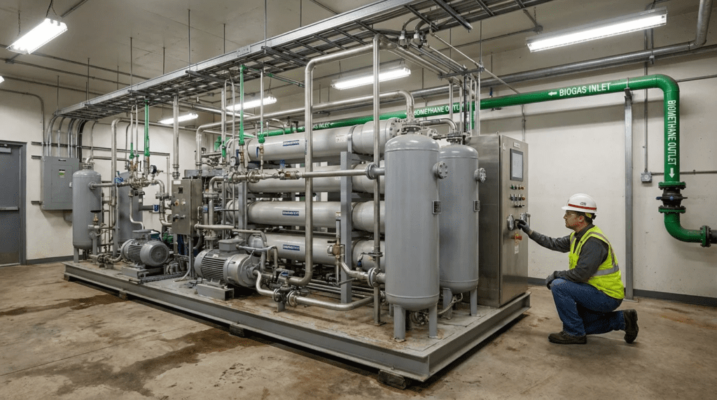
In a typical Water Resource Recovery Facility (WRRF), the biogas system encompasses the piping, valves, safety devices, conditioning skids, and storage mechanisms located immediately downstream of the anaerobic digesters. The primary operational objectives are threefold: to maintain strictly controlled pressure within the digester headspace to prevent structural damage or oxygen intrusion; to safely convey gas to combustion devices (boilers, flares, engines); and to condition the gas by removing moisture, hydrogen sulfide (H2S), and siloxanes to protect downstream generation assets.
The regulatory environment governing these systems is rigorous. Engineers must design in strict accordance with standards such as NFPA 820 (Standard for Fire Protection in Wastewater Treatment and Collection Facilities), which dictates hazardous area classifications (Class 1, Division 1 or 2) based on ventilation and gas containment. Furthermore, environmental regulations regarding methane emissions and sulfur dioxide (SO2) limits from flaring necessitate high-efficiency destruction and thorough gas scrubbing.
OEM selection in this category is uniquely critical due to the volatile nature of the medium. Unlike liquid stream processes where failure results in a spill or permit violation, failure in biogas handling (such as a flame arrester failure or pressure relief valve malfunction) can lead to catastrophic deflagration, structural rupture of digester covers, or asphyxiation hazards. Consequently, equipment must be specified based on proven reliability, precise leak-rate tolerances, and robust materials of construction capable of withstanding the highly corrosive nature of raw biogas.
2. How to Select Biogas Process Equipment
Selecting equipment for biogas systems requires a multi-disciplinary approach involving chemical, mechanical, and safety engineering principles. The “biogas system” is not a single unit but a train of components including safety relief valves, flame arresters, sediment traps, gas scrubbers, compressors, storage holders, and waste gas burners (flares). The following engineering criteria define the specification process.
Process Function and Performance Requirements
The fundamental requirement is pressure management. Anaerobic digesters typically operate at very low pressures, often between 6 to 12 inches of water column (w.c.). Equipment selection begins with a rigorous hydraulic (pneumatic) profile of the gas train. The total backpressure exerted by the piping, flame arresters, and downstream utilization equipment must not exceed the operating pressure of the digester covers. OEMs must be evaluated on the pressure drop characteristics of their components. A flame arrester with a high pressure drop may necessitate larger piping diameters or booster blowers, significantly altering the capital and operational cost profile.
Performance also dictates the selection of safety devices. Vacuum relief is as critical as pressure relief; drawing a vacuum on a digester due to rapid sludge withdrawal or thermal contraction can collapse a steel or concrete cover. Relief valves must be sized based on API 2000 standards, accounting for maximum gas generation rates and emergency pump-out scenarios.
Hydraulic and Pneumatic Loading Considerations
Biogas flow is rarely static. It fluctuates based on digestion kinetics, temperature changes, and feeding cycles. Equipment must be sized for peak instantaneous flow, not just average daily production. For gas conditioning systems, turndown ratio is a key specification. If a facility produces fluctuating gas volumes, the H2S removal system and moisture removal skids must maintain removal efficiencies across the full flow range. Engineers should specify positive displacement blowers or variable frequency drive (VFD) equipped centrifugal blowers that can match the digester gas production without creating dangerous negative pressure situations.
Materials of Construction
Raw biogas is a hostile environment. It is fully saturated with moisture and contains H2S, which forms sulfuric acid upon condensation, and CO2, which forms carbonic acid. Standard carbon steel is generally unsuitable for wetted parts unless heavily coated, which poses long-term maintenance risks. The industry standard specification is Stainless Steel 316L for all valve internals, flame arrester elements, and critical piping sections. For valve bodies and housings, aluminum may be used in lower-severity applications, but cast iron or stainless steel is preferred for durability. Diaphragms and seals must be composed of elastomers like PTFE (Teflon) or Viton that resist chemical attack and do not degrade under continuous exposure to methane and trace VOCs.
Integration with Upstream and Downstream Processes
The biogas system acts as the bridge between the biology of the digester and the mechanics of the energy plant. Integration requires careful logic programming. For example, waste gas burners (flares) must automatically modulate to maintain digester pressure when the CHP engine trips offline. If the reaction time of the flare valve is too slow, the pressure relief valves on the digester roof may lift, venting methane to the atmosphere—a reportable environmental event and a safety hazard. Engineers must verify that the OEM’s instrumentation (pressure transmitters, flow meters) integrates seamlessly with the plant SCADA system to provide real-time balancing of gas flows.
Footprint and Layout Constraints
Biogas safety equipment often requires specific installation distances to function correctly. For instance, deflagration flame arresters have a maximum “run-up” distance (the length of pipe between the ignition source and the arrester) typically limited to 50 pipe diameters or less. Exceeding this distance can allow a flame front to accelerate from a deflagration to a detonation, which most standard arresters cannot stop. Detonation arresters, which can handle supersonic flame fronts, are heavier, more expensive, and have higher pressure drops. Layout planning must prioritize placing safety equipment within certified distances, often necessitating rooftop installations or dedicated valve vaults that require classified electrical ratings.
Energy Efficiency and Operating Cost
While safety valves are passive, gas conditioning systems are active energy consumers. Gas cooling (chilling) to remove moisture requires significant refrigeration tonnage. Adsorption systems for siloxane removal impose pressure drops that increase blower horsepower requirements. When selecting gas cleaning OEMs, engineers should evaluate the lifecycle cost of media replacement. Activated carbon media for H2S removal is an expensive recurring operational cost. Biological scrubbers (bioscrubbers) offer lower operating costs but higher capital investment and more complex process control. The trade-off analysis should calculate the cost per cubic foot of treated gas over a 20-year horizon.
Operations and Maintenance Impacts
Maintenance access is frequently overlooked in biogas system design. Flame arrester elements are prone to fouling from biological foam, particulate matter, and sulfur deposits. If an arrester is installed 20 feet in the air without a service platform, it will not be cleaned, leading to blinding and eventual pressure relief activation. Engineers should specify “draw-out” or easy-access designs for arrester banks. Similarly, pressure/vacuum relief valves (PVRVs) require annual bench testing to verify set points. OEMs that offer pallet assemblies that can be easily removed or swapped in the field are preferred over units requiring complete removal from the pipe header.
Common Failure Modes
The most common failure mode in biogas systems is valve seat leakage. Due to the low operating pressures, valves rely on the weight of the pallet or a light spring to seal. Even minor corrosion or debris on the seat can cause continuous leakage of fugitive methane (odors and revenue loss). Freezing is another critical failure mode in cold climates; condensate can freeze valve pallets shut, rendering safety devices useless. OEMs addressing this with heated valve jackets, non-stick seat materials, and superior condensate drainage designs demonstrate higher reliability.
Lifecycle Cost Considerations
Initial capital cost for biogas equipment is often a fraction of the lifecycle cost. Low-cost valves often require more frequent replacement of seals and pallets. Cheap flame arresters may corrode, requiring total unit replacement rather than simple element cleaning. The highest cost, however, is the risk cost. A catastrophic failure resulting in a digester roof rupture can cost millions in repairs and months of downtime. Therefore, premium OEMs with documented third-party verification of flow curves and leak rates typically offer the lowest risk-adjusted lifecycle cost.
3. Comparison Table
The following table compares the leading OEMs for Biogas Systems. This comparison focuses on their primary areas of specialization within the biogas train—Safety/Handling, Conditioning/Cleaning, and Storage. Engineers should use this table to align specific project subsystems (e.g., flares vs. scrubbers) with the manufacturer best suited for that specific technology, rather than assuming a single vendor provides a comprehensive solution for all distinct unit processes.
| OEM Name | Typical Applications | Engineering Strengths | Limitations | Maintenance Considerations |
|---|---|---|---|---|
| Varec Biogas | Safety relief valves (PVRV), Flame arresters, Waste gas burners, Regulators. | Industry standard for durability; massive install base; modular valve designs allow easy repairs; highly accurate low-pressure control. | Primarily focused on handling/safety hardware; less focus on complex biological gas scrubbing technologies. | Simplified maintenance with replaceable seat rings and pallets; extensive spare parts availability through distribution. |
| Groth Corporation | Pressure/Vacuum relief valves, Deflagration/Detonation arresters, Pilot-operated valves. | Precision machining results in exceptionally low leak rates (bubble-tight); broad range of exotic materials for corrosive applications. | Product portfolio is heavily concentrated on valves and safety devices, requiring integration with other vendors for flares/scrubbing. | High-precision components require careful handling during service; cleaning of flame elements is straightforward but critical. |
| Shand & Jurs | Tank instrumentation, Insulation-jacketed valves, Water-sealed valves, Flares. | Excellent solutions for cold-weather climates (“All-Weather” designs); insulation jackets prevent freezing; robust “Expanda-Seal” technology. | Similar to Groth/Varec, focus is on the mechanical safety hardware rather than gas upgrading processes. | “Expanda-Seal” diaphragms provide tight sealing but require periodic inspection to ensure elasticity is maintained. |
| Evoqua (Xylem) | Gas cleaning (H2S removal), Odor control, Anaerobic Digester Covers, Geomembrane covers. | Comprehensive process solutions including biological and chemical scrubbing; strong expertise in digester cover integration. | Systems are often large, engineered packages rather than off-the-shelf components; higher capital intensity for full systems. | Media change-outs for scrubbers can be labor-intensive; biological systems require nutrient monitoring and biomass management. |
| WesTech Engineering | DuoSphere gasholders, Digester covers (steel and membrane), Gas safety integration. | Market leader in gas storage (double membrane spheres); integrates storage seamlessly with cover design and safety systems. | Primary focus is structural/storage (covers and holders) rather than standalone valve manufacturing or gas upgrading. | Membrane systems require periodic inspection for tears or UV degradation; blowers for air-ballast systems require standard maintenance. |
4. Top OEM Manufacturers
The following manufacturers represent the established tier of Original Equipment Manufacturers for biogas handling, safety, and conditioning. Selection should be based on the specific subsystem being designed (e.g., safety relief vs. gas storage) as capabilities vary significantly between these entities.
Varec Biogas
Varec Biogas is arguably the most recognizable name in the North American municipal wastewater biogas market. Their legacy dates back nearly a century, establishing the baseline standards for sewage gas handling.
- Core Technology: Varec specializes in the “hardware” of biogas control: Pressure and Vacuum Relief Valves (PVRVs), flame arresters, sediment traps, drip traps, and manometers. Their 5800 series relief valves are ubiquitous on digester covers. They also manufacture enclosed waste gas burners (flares) that comply with strict emission standards.
- Engineering Focus: The primary engineering philosophy of Varec is rugged simplicity. Their valves are designed to operate in dirty, wet, and corrosive environments with minimal intervention. They utilize weight-loaded pallets for consistent pressure relief that does not drift over time, unlike spring-loaded alternatives that may suffer from spring fatigue or hysteresis.
- Best-Fit Scenarios: Varec is the standard specification for municipal digester safety loops. They are ideal for projects requiring robust, cast-aluminum or stainless steel components that can be easily serviced by plant maintenance staff. Their waste gas burners are well-suited for standard municipal applications requiring reliable destruction efficiency without excessive complexity.
Groth Corporation
Groth Corporation acts as a direct competitor to Varec in the safety valve and flame arrester market, often distinguishing itself through precision engineering and low-leakage performance.
- Core Technology: Groth manufactures a comprehensive line of pressure/vacuum relief valves, pilot-operated valves, and flame control devices (both deflagration and detonation arresters). Their 7000 series valves are widely utilized in both industrial and municipal sectors.
- Engineering Focus: Groth emphasizes “leak rate” reduction. In biogas systems, fugitive emissions are a major concern. Groth’s valve seating technology often utilizes cushioned air-cushion pallets or superior soft-seat materials to achieve sealing capabilities that exceed API 2000 requirements. This makes them particularly attractive for facilities strictly monitoring methane emissions or seeking to maximize gas recovery for RNG projects where every cubic foot of lost gas is lost revenue.
- Best-Fit Scenarios: Groth is an excellent choice for applications requiring high-precision pressure control or where the facility is located in close proximity to residential areas where odor control (via leak prevention) is paramount. Their detonation arresters are frequently specified for long-run piping systems where flame acceleration is a calculated risk.
Shand & Jurs
Shand & Jurs (an L&J Technologies company) is another historical pillar of the tank gauging and safety valve industry. They have a particularly strong reputation for addressing environmental challenges such as freezing.
- Core Technology: The company produces PVRVs, flame arresters, emergency vents, and tank level gauging systems. A standout product is their insulation-jacketed valves and water-sealed valve designs.
- Engineering Focus: Shand & Jurs engineers solutions for extreme environments. Their “All-Weather” breathing valves utilize special non-stick coatings and insulation jackets to prevent the valve pallet from freezing to the seat—a common failure mode in northern climates that can lead to catastrophic digester over-pressurization. Their “Expanda-Seal” technology uses a unique diaphragm contour to ensure tight sealing up to 95% of the set pressure, minimizing “simmering” (minor leakage just before the valve pops).
- Best-Fit Scenarios: Engineers operating in cold climates (Northern US, Canada) should strongly consider Shand & Jurs for outdoor digester installations. Their water-sealed valve options are also beneficial in applications with extremely sticky or “dirty” gas where standard pallet-to-seat contact might be compromised by debris.
Evoqua (Xylem)
While the previous OEMs focus on valves and safety hardware, Evoqua (now part of Xylem) is a dominant force in gas conditioning, cleaning, and digester covers.
- Core Technology: Evoqua provides holistic biogas management solutions. This includes the “GeoMembrane” digester covers and comprehensive gas cleaning skids that remove H2S, moisture, and siloxanes. Their VBS (Vapor Phase Bio-Scrubber) systems are widely used for removing high concentrations of hydrogen sulfide using biological media rather than expensive chemical consumables.
- Engineering Focus: Evoqua focuses on the “process” side of biogas. Their engineering strength lies in integrating the cover (generation) with the cleaning system (conditioning). By supplying the cover, they ensure the gas collection efficiency is maximized. Their scrubbing technologies are designed for Lifecycle Cost (LCC) optimization, favoring biological treatment processes that have higher upfront costs but significantly lower long-term operating costs compared to iron sponge or activated carbon media replacements.
- Best-Fit Scenarios: Evoqua is the preferred partner for major plant upgrades involving new digester covers or greenfield gas-to-energy projects. When a facility needs to scrub high levels of H2S (e.g., >500 ppm) down to engine-ready levels (<50 ppm), Evoqua’s biological scrubbing solutions are often the most economical choice over 20 years.
WesTech Engineering
WesTech is primarily known for process equipment, but in the biogas sector, they are a market leader in gas storage and containment.
- Core Technology: WesTech’s DuoSphere gasholders are double-membrane gas storage spheres that have largely replaced steel floating covers for gas storage. They also manufacture steel digester covers (fixed and floating) capable of integrating mixing systems.
- Engineering Focus: Structural integrity and storage capacity. The DuoSphere uses an outer membrane for structural protection and an inner membrane for variable gas storage, maintained by an air blower system. WesTech engineers these systems to withstand high wind loads and snow loads while integrating the necessary safety relief systems to protect the membrane from over-inflation.
- Best-Fit Scenarios: Any facility requiring intermediate gas storage to balance the mismatch between gas production (continuous) and gas utilization (often peaking or batch). Their storage spheres are essential for maximizing the efficiency of CHP engines by creating a buffer volume.
5. Head-to-Head Equipment Comparisons
The profiles above establish where each supplier concentrates its engineering effort, but procurement usually narrows to a direct choice between two candidates that both clear the technical threshold. The comparisons below address pairings that recur on biogas and digester-gas projects, including the treatment-side equipment that frequently shares a project scope with the gas train.
Gas Conditioning Versus Chemical Dosing Approaches
Hydrogen sulfide removal can be approached from two directions: treat the gas after it leaves the digester, or dose chemically upstream to suppress sulfide formation in the first place. The comparison of Evoqua vs ProMinent biogas equipment examines suppliers on both sides of that divide — process-scale gas cleaning systems against chemical dosing and metering equipment.
The engineering trade-off is real and frequently mis-evaluated. Upstream chemical addition — typically iron salts dosed into the digester or the sludge feed — suppresses sulfide at source, requires minimal capital, and is straightforward to start and stop, but imposes a permanent chemical cost that scales with sulfur loading and adds inert mass to the digested solids. Downstream gas cleaning carries higher capital and a larger footprint but decouples the operating cost from chemical pricing, and biological scrubbing in particular substitutes nutrient dosing for continuous consumable purchase. As noted in the lifecycle discussion above, the correct comparison is cost per cubic foot of treated gas over a twenty-year horizon, and at low sulfur loadings the chemical route frequently wins on that basis despite appearing less sophisticated.
Adjacent Treatment Equipment in Combined Project Scopes
Digester and biogas projects rarely arrive as isolated scopes. Cover replacement, gas cleaning, and energy recovery are commonly bundled with sidestream treatment, odor control, or disinfection work in the same capital package, which means the supplier evaluation extends beyond gas-train equipment. The comparison of Xylem Wedeco vs Ozonia biogas equipment covers two established process-equipment brands that appear in this wider scope, both of which sit within the same corporate portfolios that supply digester covers and gas conditioning packages.
The practical consideration is package scope and single-source responsibility. As established in the integration discussion above, the biogas system spans a boundary between the biological process and the mechanical energy plant, and combined scopes push that boundary wider still. Where one supplier can furnish the cover, the gas cleaning skid, and the adjacent process equipment, the interfaces become that supplier’s problem rather than the utility’s. Where scopes are split, each interface needs an owner named in the contract documents, because the failure mode is not a defective component but two correctly functioning components that were never designed to work together.
6. Application Fit Guidance
Selecting the right OEM requires matching the manufacturer’s strength to the facility’s specific needs. One manufacturer rarely provides the “best” solution for every component in the gas train.
Municipal Wastewater Treatment
For standard municipal plants, reliability and ease of maintenance are paramount. Varec Biogas is often the default choice for the “safety loop” (PVRVs, arresters) due to familiarity among operators and universal spare parts availability. If the plant is in a severe freeze zone, Shand & Jurs jacketed valves should be specified for outdoor rooftop installations. For gas storage, WesTech dual-membrane spheres are the modern standard, replacing older steel floating gas holders which are maintenance-intensive.
Industrial Wastewater & High H2S Applications
Industrial anaerobic systems (e.g., food and beverage, breweries) often produce biogas with significantly higher H2S concentrations than municipal sludge. Here, material compatibility is critical. Groth Corporation offers excellent material options (Hastelloy, etc.) for safety valves. For the cleaning of this sour gas, Evoqua’s biological scrubbers are highly recommended to handle the high sulfur loading without bankrupting the facility on media replacement costs.
RNG (Renewable Natural Gas) Projects
RNG projects require the strictest gas quality and leakage control. The value of the gas is high, making fugitive emissions costly. Groth Corporation is often favored here for safety valves due to their superior seat tightness (10% of API 2000 allowable leakage). For the conditioning systems upstream of membrane separation, Evoqua or specialized gas train integrators are necessary to remove siloxanes to non-detectable levels.
Retrofit vs. Greenfield
In retrofit applications, footprint is a major constraint. Varec and Groth offer inline flame arresters and valves that can be easily swapped into existing piping galleries. For greenfield sites, engineers have the luxury of designing optimal spacing. This favors large-scale biological scrubbers from Evoqua and separate gas storage spheres from WesTech, rather than trying to store gas under the digester cover itself.
7. Biogas Fundamentals and Process Context
Equipment specification rests on assumptions about gas volume, composition, and consistency that are properties of the digestion process rather than the hardware. The subsections below cover the upstream context that determines whether the gas train is sized correctly.
Biogas as an Energy Resource
The economics that justify a gas train depend on what the gas is worth and how reliably it is produced. A grounding in biogas as a renewable energy resource — formation chemistry, typical methane fractions, energy content per unit volume, and the utilisation pathways available — establishes the framework within which safety and conditioning equipment is justified.
The number that matters most for equipment sizing is methane fraction, which typically falls in the range of 60 to 65 percent for municipal sludge digestion and varies more widely for industrial substrates. That fraction sets the heating value, which in turn sets the CHP or boiler capacity and therefore the peak gas demand the train must supply. A conditioning skid sized against an optimistic methane fraction will be undersized in practice, and the shortfall shows up as flaring rather than generation.
Gas Generation from Wastewater Sludge
Predicting how much gas a facility will actually produce is the first step in sizing every downstream component. The mechanisms behind biogas from wastewater — volatile solids destruction, retention time, temperature regime, and substrate characteristics — determine both the average production rate and the variability the equipment must absorb.
Volatile solids destruction is the governing variable, commonly falling between 45 and 60 percent for mesophilic digestion of municipal sludge, with roughly 12 to 18 cubic feet of gas produced per pound of volatile solids destroyed. Facilities accepting high-strength organic waste through co-digestion see substantially higher and more variable production, which is precisely the condition that makes storage volume and turndown ratio decisive rather than incidental. Sizing on average daily production without accounting for feeding-cycle peaks is the most common origin of undersized relief and conditioning capacity.
Plant-Wide Integration of Digester Gas
Gas production and gas demand are rarely synchronised, and the mismatch is what the storage and flare systems exist to absorb. A broader view of biogas in wastewater treatment operations covers how digester gas fits into overall plant energy balance, heat recovery for digester heating, and the operational decisions that determine how much of the produced gas is actually used rather than flared.
The practical measure worth tracking is beneficial use fraction — the proportion of produced gas that reaches a useful end rather than the flare. Facilities frequently discover that this figure is far lower than assumed, with losses concentrated in start-up and shutdown transitions, engine outages, and periods when digester heating demand and gas production are out of phase. Improving that fraction is often cheaper than expanding production, and it usually turns on storage volume and control logic rather than on new equipment.
8. Engineer & Operator Considerations
Beyond the catalog specifications, the long-term success of a biogas system relies on practical implementation strategies.
Installation and Commissioning
A critical oversight in biogas design is the failure to pressure-test the piping system before introducing gas. The system operates at such low pressures that standard hydrostatic testing is inappropriate; pneumatic testing with low-pressure air and soap solution on joints is required. Engineers must specify that safety relief valves are isolated or removed during pipe pressure testing, as test pressures often exceed the sensitive settings of the relief pallets, potentially damaging them before operation begins.
Maintenance Access and Safety
Flame arresters are passive devices, but they are not “install and forget.” The narrow crimped metal ribbons (the element) that stop flames act as excellent filters for particulate and grease. If they clog, digester pressure rises, lifting relief valves and venting odors. Operators must have safe access—platforms, not ladders—to remove these heavy elements for cleaning. Design the piping with “spool pieces” or jackscrews to allow for easy removal of the arrester element without springing the piping.
Spare Parts and Redundancy
For critical safety valves, the “N+1” philosophy is challenging because you cannot simply install a standby relief valve on a digester roof (both must be active to handle emergency flows). Therefore, the spare parts strategy is vital. Facilities should stock a complete set of replacement pallets and flame arrester elements. Cleaning a flame arrester element can take hours of soaking in solvent; having a clean spare ready to swap in immediately reduces downtime from hours to minutes.
Condensate Management
Biogas is 100% humid. As it cools in the piping, it drops significant water volume. Piping must always slope back to the digester or to dedicated drip traps (sediment traps). A common design error is installing a safety valve at a low point in the piping; condensate will accumulate on top of the valve pallet, artificially increasing the set pressure (water column weight) and preventing the valve from opening when needed. Always install safety devices at high points or ensure positive drainage away from the valve seat.
9. Conclusion
Specifying biogas systems is a high-stakes engineering task where the margin for error is measured in inches of water column. The selection of OEMs must prioritize safety and reliability above all else. For the foundational safety hardware—relief valves and flame arresters—Varec Biogas, Groth Corporation, and Shand & Jurs represent the industry triumvirate, each with distinct strengths in durability, precision, and weather resilience, respectively. For the increasing complexity of gas conditioning and storage, Evoqua and WesTech provide the process-heavy solutions required for modern energy recovery.
Engineers are advised to treat the biogas train not as a collection of pipes, but as a dynamic pressure vessel system. Success lies in calculating accurate pressure drops, selecting materials compatible with the sour gas environment, and ensuring that the selected equipment can be practically maintained by the operations staff who will inherit the system. By aligning the unique strengths of these top OEMs with the specific hydraulic and environmental constraints of the project, engineers can deliver biogas systems that are safe, compliant, and energy-positive.