
VAG
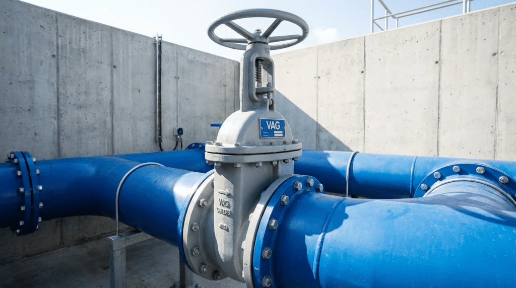
Introduction to VAG Flow Control Technologies
One of the most persistent challenges in municipal and industrial water infrastructure is the management of high-energy water streams without inducing catastrophic mechanical failure. Engineers frequently underestimate the destructive power of cavitation and water hammer, leading to premature valve degradation and pipeline ruptures. Within the global water sector, VAG has established itself as a supplier of heavy-duty flow control and isolation solutions, particularly in high-pressure applications such as dams, transmission mains, and power plants. However, the effectiveness of any valve relies entirely on precise specification and hydraulic alignment.
VAG equipment appears in critical infrastructure from the bottom outlets of hydroelectric dams to the distribution networks of major metropolitan areas. Yet a common oversight in the design phase is treating these complex hydraulic machines as simple commodities. The distinction between a standard shut-off valve and a control valve engineered for continuous throttling is significant, often measured in substantial lifecycle costs. For consulting engineers and utility directors, understanding the engineering principles behind VAG valves and similar high-performance equipment is essential for preventing operational bottlenecks.
This article provides a specification-safe analysis of VAG flow control technologies, designed to help engineers navigate sizing, material selection, and integration.
Editorial note: two formulas on this page previously published as unrendered markup rather than as equations, and have been rewritten in plain notation below. Ownership in the European valve sector has also changed hands repeatedly in recent years; verify VAG’s current corporate ownership and North American representation before writing the name into a specification.
This guide sits within our coverage of top valve manufacturers. See also our discussion of valve and actuator procurement strategy, and our roundups of valve construction service manufacturers and valve service manufacturers.
How to Select and Specify VAG Valves
Selecting the correct valve requires a departure from simple line-size matching. Engineers must evaluate the full hydraulic profile and mechanical constraints of the application.
Duty Conditions & Operating Envelope
The primary driver for selection is the specific duty cycle. For isolation applications, the valve is expected to be either fully open or fully closed. However, for control applications, the operating envelope is dynamic. Engineers must define:
- Differential Pressure: The pressure drop across the valve in modulated positions. High differential pressure at low flow rates is the primary cause of cavitation.
- Flow Velocity: Exceeding 4 to 5 m/s in isolation valves can lead to vibration and seat damage. Control valves such as plunger valves are designed to handle significantly higher velocities at the seat area without damage.
- Frequency of Operation: A valve modulated continuously by a control loop requires a different actuation and bearing design than a valve cycled once annually.
Specification error: using a butterfly valve for high-pressure-drop throttling often results in cavitation damage within months. For high differential pressure applications, a plunger or needle valve is the hydraulically correct choice.
Materials & Compatibility
The longevity of VAG valves in wastewater or raw water applications depends heavily on material science. Standard ductile iron is sufficient for the body, but the internal wetted parts and coatings require scrutiny.
- Coatings: In potable water, heavy-duty epoxy powder coating, often GSK certified, with a minimum thickness of 250 microns is the baseline. For wastewater with high hydrogen sulfide concentrations, internal linings may need to be ceramic-filled epoxy or glass-lined.
- Seating Surfaces: For gate valves, EPDM rubber encapsulation is standard. However, in industrial wastewater containing hydrocarbons, nitrile is required to prevent swelling.
- Shafts and Stems: Duplex stainless steel (1.4462) is recommended for critical shafts to resist stress corrosion cracking, particularly in chloride-rich environments.
Hydraulics & Process Performance
Hydraulic performance is quantified by the valve’s flow coefficient and its inherent flow characteristic curve. When specifying control valves, engineers must analyze the system curve against the valve curve.
- Linear vs. Equal Percentage: Plunger valves typically offer linear control characteristics, meaning flow changes linearly with stroke. This is well suited to discharging to atmosphere. Butterfly valves typically exhibit an approximately equal percentage characteristic, where flow changes disproportionately near the closed position.
- Cavitation Index: Engineers must calculate the cavitation index for the worst-case operating point. If it falls below the critical value for the valve, anti-cavitation trim such as a slotted cage must be specified.
Installation Environment & Constructability
Physical constraints often dictate valve selection. Large diameter butterfly valves save significant space compared to gate valves, but they require specific upstream and downstream straight pipe runs, typically three to five pipe diameters, to ensure a uniform velocity profile and prevent flutter.
- Orientation: While many valves can be installed vertically or horizontally, large gate valves often require horizontal installation with the stem horizontal to prevent debris accumulation in the bottom track.
- Support: Heavy plunger valves and large gate valves impose significant dead loads. Concrete plinths or dedicated pipe supports must be detailed in the civil drawings to prevent stress transfer to the pipe flanges.
Reliability, Redundancy & Failure Modes
In critical transmission mains, the failure mode of the valve is a safety parameter. Combined air valves, for instance, play a critical role in preventing pipeline collapse during vacuum conditions.
- Service Life: High-quality valves should operate for 25 to 50 years. The weakest links are typically the actuator and the resilient seals.
- Safety Factors: Actuators should be sized with a safety factor of 1.25 to 1.5 times the maximum seating torque to account for breakaway torque after long periods of inactivity.
Controls & Automation Interfaces
- Actuation: Multi-turn electric actuators are common for gate and plunger valves; quarter-turn for butterfly valves. Specifications must define the interface protocol.
- Position Feedback: Accurate position transmitters are vital for control loops. Non-contact encoders are preferred over potentiometers for durability.
Maintainability, Safety & Access
- Access Platforms: If the handwheel or actuator controls are more than 1.5 meters above grade, permanent compliant platforms should be included in the design.
- Confined Space: For valves in vaults, ensure the vault hatch is sized to allow removal of the entire valve assembly, or at least the internal mechanism, without demolition.
Lifecycle Cost Drivers
- Head Loss: A full-bore gate valve has negligible head loss. A butterfly valve disc obstruction creates permanent pressure loss, increasing pumping energy costs over the lifecycle.
- Maintenance Labor: Valves that allow in-situ seal replacement without removing the body from the line significantly reduce maintenance costs.
Valve Technology Comparison Guide
Table 1: Flow Control & Isolation Technology Comparison
| Valve Type | Primary Strengths | Best-Fit Applications | Limitations & Considerations | Typical Maintenance |
|---|---|---|---|---|
| Plunger / Needle Valves | Precise linear flow control; high cavitation resistance; anti-cavitation trim options. | Dam bottom outlets; high-pressure reduction; reservoir inlet control; turbine bypass. | High capital cost; heavy weight; requires substantial installation space; complex mechanism compared to gates. | Seal replacement; mechanism lubrication; intervals of 5 to 7 years. |
| Resilient Seated Gate Valves | Full bore; bidirectional sealing; robust design; debris tolerant. | Wastewater isolation; water distribution networks; buried service; pump isolation. | Poor throttling capability; large number of turns to close; heavy footprint in large diameters. | Stem seal replacement; exercising to prevent seizure; intervals of 1 to 3 years. |
| Butterfly Valves (Double Eccentric) | Compact; lightweight; quick quarter-turn operation; cost-effective in large diameters. | Transmission mains; treatment plant galleries; filter isolation; low-head control. | Disc obstructs flow; susceptible to cavitation at high differential pressure; requires straight pipe run upstream. | Seat adjustment or replacement; actuator maintenance; intervals of 3 to 5 years. |
| Air Release / Vacuum Valves | High venting capacity; combined release, vacuum break, and micro-venting functions. | High points in pipelines; pump discharge; long transmission lines; deep well applications. | Must be sized correctly to prevent water hammer; float mechanisms can foul in wastewater. | Cleaning of float and orifice; seal inspection; intervals of 6 to 12 months in wastewater. |
Table 2: Application Fit Matrix
| Application Scenario | Plunger Valve | Gate Valve | Butterfly Valve | Knife Gate Valve | Key Constraint |
|---|---|---|---|---|---|
| Raw Sewage Isolation | Not Recommended | Excellent | Poor (clogging risk) | Good | Solids Handling |
| Potable Water Transmission (High Pressure) | Good (control) | Good (isolation) | Excellent (isolation) | Not Recommended | Pressure Rating / Size |
| Pressure Regulation / Throttling | Best Fit | Do Not Use | Conditional (low differential pressure) | Do Not Use | Cavitation / Linear Control |
| Dam Bottom Outlet | Best Fit | Conditional (guard valve only) | Conditional (guard valve only) | Not Recommended | Extreme Velocity / Energy Dissipation |
Engineer and Operator Field Notes
Commissioning & Acceptance Testing
- End Stop Settings: Ensure the actuator limit switches are set correctly. For metal-seating valves such as wedge gate valves, the closed position should often be torque-seated, while the open position is position-seated. For resilient-seated valves, position seating protects the elastomer.
- Stroke Timing: Adjust the opening and closing time to prevent water hammer. A large plunger valve may need 60 to 120 seconds to close to safely dissipate energy in a long pipeline.
- Dry vs. Wet Testing: Never fully stroke a high-performance control valve dry if it relies on the fluid for lubrication or cooling of the dynamic seals, unless approved by the manufacturer.
Over-torquing is a leading cause of valve stem damage. Always request the Maximum Allowable Stem Torque from the manufacturer and ensure the actuator’s stall torque does not exceed this value.
Common Specification Mistakes
- Ignoring the Gearbox: Specifying a high-grade valve body but failing to specify the ingress protection rating or coating of the gearbox often leads to the gearbox failing before the valve.
- Incomplete Coating Specs: Simply stating “epoxy coated” is insufficient. Specify the coating standard, the minimum thickness, and holiday-free testing.
- Undersizing Air Valves: Failing to account for the vacuum collapse pressure of the pipe. The air valve intake capacity is often more critical than its exhaust capacity.
O&M Burden & Strategy
- Exercise Program: Isolation valves that sit in one position for years will eventually seize. Implement a semi-annual exercising program to keep the screw and nut free of calcification.
- Gearbox Lubrication: Check oil levels in gearboxes annually. Water ingress into gearboxes is common in flooded vaults; consider IP68 rated gearboxes for these environments.
- Spares Inventory: For critical plunger valves, keep a set of primary seals and a seat ring on the shelf. Lead times for custom components can be lengthy.
Troubleshooting Guide
Symptom: Vibration or noise during throttling.
Root Cause: Cavitation or operation below minimum opening percentage.
Fix: Check the cavitation index. If cavitation is present, air admission may be required, or the valve is oversized and operating too close to the seat.
Symptom: Valve fails to seal tight.
Root Cause: Debris trapped in the seat or a worn seal ring.
Fix: Flush the valve by cycling open and closed. If persistent, verify torque switch settings are not tripping prematurely.
Design Details and Calculations
Sizing Logic & Methodology
For control valves, do not size based on line diameter. Size based on the required flow coefficient.
- Determine Flow Conditions: Define minimum, normal, and maximum flow along with the associated upstream and downstream pressures.
- Calculate the required flow coefficient: In metric practice, the flow coefficient Kv equals the flow rate in cubic metres per hour divided by the square root of the pressure drop in bar. In US practice, Cv equals the flow in gallons per minute multiplied by the square root of specific gravity divided by pressure drop in psi. Keep units consistent and state which convention the specification uses.
- Select Valve Size: Choose a valve where the calculated maximum coefficient is approximately 80 to 90 percent of the valve’s fully open rating. This ensures control authority.
- Check Velocity: Ensure the velocity at the inlet flange does not exceed the manufacturer’s limit.
A Note on Specifying a Single Manufacturer
This page describes one manufacturer’s product range, which raises a procurement point worth stating plainly. Most public agencies cannot lawfully sole-source a valve to a named manufacturer without documented justification, and a specification built around one company’s distinctive features will either be challenged or will draw non-compliant bids that the engineer then has to evaluate anyway.
The durable approach is to specify the capability rather than the product name:
- Instead of naming a plunger valve line, specify linear flow characteristic, the required flow coefficient at design conditions, and the cavitation performance demonstrated by testing.
- Instead of naming a coating brand, specify the coating standard, minimum dry film thickness, and holiday-free verification.
- Instead of naming a shaft alloy by supplier designation, specify the material grade and the corrosion performance required.
Written that way, a specification remains defensible, admits every manufacturer capable of meeting it, and still excludes the light-duty substitutions it was written to keep out.
Specification Checklist
- Design Standard: EN 1074, AWWA C504 for butterfly valves, AWWA C509 or C515 for gate valves, or specific manufacturer standards for plunger valves.
- Flange Drilling: Explicitly state ISO PN10/16/25 or ANSI Class 150/300. Mismatched flanges are a common site issue.
- Testing: Require hydrostatic shell and seat leakage testing per EN 12266-1 or the applicable AWWA standard.
- Documentation: Require 3.1 material certificates per EN 10204 for body and shaft.
Cavitation Analysis
For high pressure drops, calculate the cavitation index. One widely used definition expresses it as the downstream pressure minus the fluid vapour pressure, divided by the pressure drop across the valve:
σ = (Pdownstream − Pvapour) ÷ (Pupstream − Pdownstream)
Compare the calculated value against the valve’s tested critical and incipient-damage limits. Note that several definitions of the cavitation index are in circulation, and a manufacturer’s published limit is only meaningful when compared against a value calculated the same way. Confirm which definition the manufacturer’s data uses before comparing numbers. If the calculated value falls below the valve’s limit, cavitation will occur, and a plunger valve with an anti-cavitation cage is required to stage the pressure drop.
Frequently Asked Questions
What is the primary advantage of a plunger valve over a butterfly valve?
The primary advantage is the linear control characteristic and resistance to cavitation. A plunger valve controls flow via an axially moving piston that changes the annular cross-section. This design allows for high pressure drops without the cavitation damage that would destroy a butterfly valve disc or seat. Furthermore, the flow remains symmetrical, preventing vibration.
How often should resilient seated gate valves be maintained?
Resilient seated gate valves are generally maintenance-free regarding internal parts. However, they should be exercised at least once every 6 to 12 months to prevent the wedge nut from seizing on the stem and to clear sediment buildup in the seat area. Stem seals should be inspected annually for leakage.
What is the difference between a kinetic air valve and an automatic air valve?
A kinetic air valve, with a large orifice, is designed to exhaust or admit large volumes of air during filling or draining of a pipeline. An automatic air valve, with a small orifice, releases small pockets of accumulated air while the pipeline is pressurized and operating. Combination air valves integrate both functions into a single unit.
Why is a certified coating standard important?
Rigorous epoxy powder coating standards in the water industry specify minimum thickness, low porosity, and high adhesion. Specifying certification ensures the valve body is protected against corrosion and minimizes biofilm formation, which is critical for a long design life.
Can these valves be installed in vertical pipelines?
Most can. However, for large gate valves and check valves, gravity affects the internal components. It is crucial to specify the flow direction and the installation orientation during ordering so the manufacturer can adjust counterweights or internal guides accordingly.
How do I prevent water hammer when closing a large valve?
Water hammer is prevented by controlling the closing speed. The effective closure time, the time to close the hydraulically effective part of the stroke, usually the last 20 to 30 percent, is critical. Engineers should perform a transient analysis to determine the minimum safe closure time and program the actuator or install a dual-speed gearbox to slow closure near the seat.
Conclusion
Key Takeaways for Engineers
- Selection is Math, Not Guesswork: Use flow coefficient and cavitation index calculations to size control valves; do not rely on line size.
- Right Tool for the Job: Use plunger valves for high differential pressure throttling, gate valves for isolation, and butterfly valves for low-head space-constrained isolation.
- Material Integrity: Insist on certified epoxy coatings and appropriate stainless steel grades for shafts.
- Actuation Safety: Size actuators with a safety factor above the seating torque, but never above the Maximum Allowable Stem Torque.
- Verify Interfaces: Confirm flange drilling standards and SCADA communication protocols early in the design phase.
The specification of VAG valves and similar heavy-duty flow control equipment represents a critical decision point in water infrastructure design. While the initial capital cost of high-performance plunger or gate valves may be higher than standard alternatives, the return is realized through operational reliability, reduced leakage, and minimized energy losses.
For municipal and industrial engineers, the goal is to create a system where the valve is the strongest link, not the failure point. By adhering to rigorous hydraulic modeling, selecting materials appropriate for the fluid chemistry, and implementing a disciplined maintenance strategy, utilities can ensure their flow control assets deliver performance for decades.