
Henry Pratt vs Val-Matic Altitude Valves Equipment: Comparison & Best Fit
Introduction
One of the most visible failures in municipal water distribution is the overflow of an elevated storage tank. Beyond the public embarrassment of a “waterfall” cascading down a tower in the town center, the engineering consequences include structural icing loads in winter, erosion at the foundation, and significant wasted pumping energy. While SCADA systems provide active monitoring, the last line of mechanical defense remains the altitude valve—a pilot-operated control valve designed to close automatically at a pre-set water level.
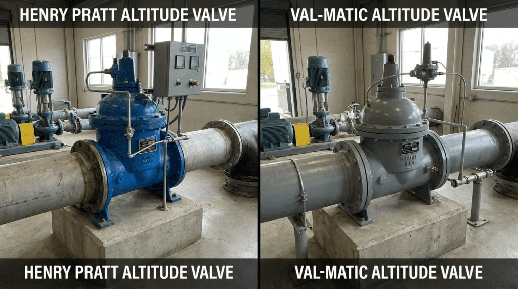
For consulting engineers and utility directors, selecting the correct mechanical safeguard is not merely a matter of brand preference; it is a calculation of reliability, hydraulic performance, and maintainability. When evaluating Henry Pratt vs Val-Matic Altitude Valves Equipment: Comparison & Best Fit, engineers are often choosing between two distinct engineering philosophies within the AWWA C530 standard framework. While both manufacturers are titans in the waterworks industry, their approaches to pilot system design, body geometry, and component accessibility differ in ways that directly impact Operational Expenditure (OPEX) and failure modes.
This article provides a rigorous, non-promotional technical analysis. We will strip away marketing claims to examine the wet-end construction, pilot sensitivity, and long-term serviceability of these valves. This pairing is one of several that recur across the supplier field for altitude valves, where the practical shortlist is narrow and each manufacturer has established defensible ground in particular service conditions. Whether you are retrofitting a 1950s-era reservoir vault or designing a new composite elevated tank, understanding the nuances of these equipment options is critical for ensuring system stability and preventing catastrophic overflow events.
The Altitude Valve Manufacturer Landscape
Altitude valve procurement rarely comes down to a single head-to-head. Most specifications name two or three acceptable manufacturers, and the pairings that appear on a bid list tend to sit at different points on a spectrum defined by how the valve is actuated and controlled. Henry Pratt and Val-Matic both represent the classical hydraulic approach: a diaphragm-actuated main valve governed by a pilot array that senses tank level and modulates the cover chamber. Other manufacturer pairings enter the same conversation from an actuation-first direction, which changes the failure modes, the maintenance skill set required, and the infrastructure the vault has to support.
Understanding where each manufacturer sits on that spectrum is what makes the Pratt-versus-Val-Matic decision tractable. The same evaluation criteria—control authority at the design flow, behavior under cavitating conditions, susceptibility to pilot fouling, serviceability without pipeline removal, and the availability of a positive remote override—apply to every pairing. What changes is which criteria dominate.
Bray and Rotork: Actuation-Led Alternatives
The comparison of Bray vs Rotork altitude valves equipment approaches tank level control from a fundamentally different premise than the hydraulic pilot systems examined here. Rather than relying on a pilot array to sense head and translate it into diaphragm position, actuation-led solutions place an electric or electro-hydraulic actuator on a butterfly or eccentric plug valve and derive the closure command from a level transmitter and control logic. Bray’s contribution to this pairing is typically the valve body and resilient seating; Rotork’s is the actuator, positioner, and control interface, including modulating duty and fail-safe provisions.
The engineering trade is explicit. Actuation-led control eliminates the pilot system, which is the dominant failure point in classical altitude valves—no small orifices to clog, no sensing line to freeze, no diaphragm to fatigue. In exchange, it introduces a power dependency, an actuator with its own maintenance and obsolescence profile, and a reliance on instrumentation that must itself be calibrated and validated. For a remote tower with no reliable power drop, the hydraulic pilot valve remains the stronger answer. For a site with existing SCADA, dependable power, and a requirement for modulated fill rate or peak-shaving control, the actuated approach offers capabilities the pilot valve cannot match without bolt-on solenoids and limit switches.
Engineers evaluating Henry Pratt against Val-Matic should read this comparison as a check on whether the problem is actually a valve selection problem. If the driver is precision level control, remote setpoint changes, or integration into a broader distribution optimization scheme, the answer may lie outside the pilot-operated category entirely. If the driver is passive, unpowered reliability at a remote asset, the classical altitude valve remains correct and the Pratt-versus-Val-Matic analysis that follows is the relevant one.
Reading the Comparisons Together
Taken as a set, these manufacturer comparisons describe a decision lattice rather than a ranking. Ubiquity of support and familiarity to maintenance crews point toward Henry Pratt. Engineered precision, flow-path refinement, and severe-service trim point toward Val-Matic. Powered modulation, remote setpoint authority, and freedom from pilot fouling point toward the actuation-led pairing. A specification that names alternates drawn from different points on this lattice gives the utility genuine competition; one that names three functionally identical products gives only the appearance of it.
How to Select and Specify Altitude Valves
Proper specification of altitude valves requires moving beyond simple line-size matching. The valve must modulate or close effectively under varying system pressures without inducing water hammer or suffering from cavitation damage. The following criteria are essential when conducting a Henry Pratt vs Val-Matic Altitude Valves Equipment: Comparison & Best Fit analysis for your specific application.
Duty Conditions & Operating Envelope
The operating envelope of an altitude valve is defined by the interaction between the distribution system pressure and the static head of the tank. Engineers must define:
- Differential Pressure (ΔP): The valve must operate effectively at both minimum ΔP (when the tank is nearly full and pump pressure is lowest) and maximum ΔP (when the tank is empty and pump pressure is highest).
- Flow Characteristics: Is the valve One-Way (fill only) or Two-Way (fill and draw)? Two-way valves require a check feature (return flow capability) that opens when distribution pressure drops below tank head.
- Fill Rates: High fill rates can lead to turbulence and sensing errors in the pilot line. Specifications must verify that the valve maintains stable operation at the maximum projected pump run-out flow.
- Transition Speed: The closing cycle must be slow enough to prevent surge, yet fast enough to prevent overflow.
Materials & Compatibility
Altitude valves in municipal service are typically constructed of Ductile Iron (ASTM A536). However, the internal trim and pilot system materials are the primary drivers of longevity.
- Body & Cover: Ductile iron with fusion-bonded epoxy (AWWA C550) is the industry standard to prevent tuberculation.
- Seat Rings: Stainless steel (316 or 304) seat rings are mandatory to resist wire-drawing erosion during the final moments of closure.
- Pilot Tubing: While copper tubing is common, specifications should call for 316 Stainless Steel tubing and fittings for any vault liable to flood or in corrosive atmospheres.
- Elastomers: EPDM is standard for potable water. However, if the water has high chloramine content, verify the elastomer grade to prevent premature degradation or swelling which can cause pilot hysteresis.
Hydraulics & Process Performance
The hydraulic design focuses on the valve’s flow coefficient (Cv) and its cavitation index. A common error is sizing the valve to match the pipe size (e.g., a 12-inch valve on a 12-inch line). Often, a smaller valve (e.g., 10-inch) provides better control authority and reduces hunting.
- Cavitation Analysis: When an altitude valve throttles near the closed position, the pressure drop across the seat increases. If the pressure drops below the vapor pressure, cavitation occurs. Manufacturers like Henry Pratt and Val-Matic offer anti-cavitation trims (slotted cages) to mitigate this.
- Head Loss: In two-way flow applications, the passive head loss through the valve during the “draw” cycle (outflow) is critical. Excessive loss here reduces system pressure during peak demand/fire flow events.
Installation Environment & Constructability
Altitude valves are frequently installed in underground vaults or at the base of towers where space is at a premium.
- Face-to-Face Dimensions: Retrofit projects often require valves that match ANSI B16.10 dimensions. Verify if the manufacturer offers standard globe or angle body configurations that fit existing piping gaps.
- Pilot System Orientation: The pilot system (the array of small tubes and controls on the side of the valve) is fragile. Designs that protect the pilot system within the valve footprint are superior to those where tubing protrudes significantly, risking damage during installation.
- Isolation: Isolation valves (gate or butterfly) must be installed upstream and downstream to facilitate maintenance.
Reliability, Redundancy & Failure Modes
The primary failure mode of an altitude valve is rarely the main valve body; it is the pilot system. Small orifices in the pilot controls are susceptible to clogging from debris, causing the valve to stick open (overflow) or closed (no fill).
- Strainer Requirement: A high-quality Y-strainer on the pilot supply line is non-negotiable.
- Diaphragm Reliability: The main valve is typically actuated by a diaphragm. Diaphragm fatigue can lead to rupture. Val-Matic and Henry Pratt utilize different diaphragm reinforcement technologies (e.g., nylon reinforced) to extend cycle life.
- MTBF: Mean Time Between Failures is heavily dependent on water quality (turbidity/particulates) rather than just mechanical cycles.
Controls & Automation Interfaces
Modern altitude valves are rarely purely hydraulic. They often interface with SCADA.
- Solenoid Override: A solenoid can be added to the pilot system to force the valve closed remotely via SCADA, regardless of tank level. This is useful for “peak shaving” or forcing turnover in the system.
- Limit Switches: Mechanical switches installed on the valve stem provide positive feedback to the control room, confirming whether the valve is actually open or closed.
Maintainability, Safety & Access
Operators must be able to service these valves safely.
- Top Entry: Both manufacturers generally offer top-entry designs, allowing internal components (seat, disc, diaphragm) to be replaced without removing the valve body from the pipeline.
- Lifting Lugs: For valves 6 inches and larger, integral lifting lugs on the cover are essential for safe disassembly.
- Bleed Cocks: Provisions for safely bleeding air from the upper cover chamber are necessary for stable operation.
Lifecycle Cost Drivers
Initial CAPEX for altitude valves is relatively low compared to pumps, but the OPEX can be significant if frequent rebuilding is required.
- Spare Parts: Rubber goods kits (diaphragms, O-rings, seat discs) are consumables. Compare the cost and availability of these kits between Pratt and Val-Matic.
- Energy Cost: High head loss through the valve equates to wasted pumping energy. Selecting a valve with a high wide-open Cv value reduces long-term electrical costs.
Selection & Specification Framework
The criteria above are individually familiar to most waterworks engineers. What produces poor outcomes is applying them in the wrong order—most commonly, starting from the line size and a preferred manufacturer, then writing performance language around that choice. The sequence below inverts that, treating manufacturer selection as an output rather than an input.
Step 1: Confirm the Control Philosophy Before the Valve
Decide first whether the site requires passive hydraulic control or powered modulated control. Passive control suits remote towers, sites without reliable power, and utilities whose maintenance crews are mechanically rather than instrumentation oriented; it points to a pilot-operated altitude valve from Pratt, Val-Matic, or a comparable manufacturer. Powered control suits sites with existing SCADA and a need for remote setpoint authority, fill-rate modulation, or coordinated operation across multiple tanks. Making this decision explicitly, and documenting the rationale, prevents the common outcome of a hydraulic valve retrofitted with enough solenoids and switches to approximate an actuated valve at greater complexity and lower reliability.
Step 2: Establish the Differential Pressure Envelope
Tabulate inlet pressure and tank static head at four conditions: tank empty with pumps at maximum output, tank empty at minimum supply pressure, tank near overflow at maximum supply, and tank near overflow at minimum supply. The last case governs whether the valve can still close tightly, since pilot-operated valves require a minimum differential—commonly in the range of 5 to 10 psi—to develop the force needed to seat. Short tanks fed by marginal supply pressure are the classic failure scenario, and no manufacturer selection fixes a valve that has insufficient differential to operate.
Step 3: Worked Cv and Control Authority Example
Consider a 12-inch fill line to a 120-foot elevated tank, with a design fill rate of 1,400 gpm and an inlet pressure of roughly 75 psi at that flow. The tank static head near overflow is approximately 52 psi, leaving a differential across the valve of about 23 psi at the design condition. For water at a specific gravity of 1.0, the required flow coefficient is the flow divided by the square root of the differential—1,400 divided by the square root of 23, or approximately 292. A 12-inch globe-pattern control valve may carry a wide-open Cv well above 1,000, meaning the valve would operate at under 30 percent of its capacity and spend its life throttling near the seat, where control is least stable and cavitation risk is highest. A 10-inch or even 8-inch body with a wide-open Cv in the 330 to 400 range places the required 292 at roughly 75 to 85 percent of capacity, which is the target band. The valve is then genuinely modulating rather than acting as a partially cracked orifice, hunting is reduced, and seat erosion falls. Reducers to the smaller body add modest head loss that is far outweighed by the control improvement.
Step 4: Run the Cavitation Screen
Compare inlet and outlet absolute pressures across the valve at the throttled conditions, not just wide open. Where the ratio of inlet to outlet pressure approaches or exceeds roughly 3 to 1, specify anti-cavitation trim and require the manufacturer to submit cavitation coefficient data for the selected size and trim rather than a generic product statement. Cavitation damage in altitude valves concentrates at the seat, which is precisely the surface that must seal tightly to prevent overflow—the failure is therefore progressive and self-reinforcing.
Step 5: Screen on Pilot Protection and Serviceability
Because pilot fouling dominates the failure statistics, rank candidates on how well the pilot system is protected and how easily it is serviced. Look for isolation ball valves on every pilot leg so a pilot can be rebuilt without draining the main line, generous strainer capacity with accessible cleanout, stainless tubing and fittings, and a sensing tap location that can be taken from a still region rather than the turbulent fill pipe. Confirm that top-entry service is possible within the vault’s actual clear height, measured rather than assumed.
Step 6: Compare on Twenty-Year Cost
Build the comparison from installed capital, rubber goods kit cost and expected replacement interval, labor hours per rebuild including vault entry, the pumping energy implied by head loss at the wide-open condition over the annual fill volume, and the expected cost of a single overflow event weighted by its likelihood under each design. That last term is where anti-cavitation trim and pilot redundancy usually justify themselves, and it is the term most often omitted from a bid comparison.
Technical Comparison Tables
The following tables provide a structured comparison to assist in the Henry Pratt vs Val-Matic Altitude Valves Equipment: Comparison & Best Fit decision-making process. Table 1 focuses on the equipment characteristics, Table 2 outlines application suitability, and Table 3 positions both manufacturers against the actuation-led alternative discussed earlier.
| Feature / Attribute | Henry Pratt (Control Valve Series) | Val-Matic (Control Valve Series) |
|---|---|---|
| Primary Design Architecture | Typically Globe or Angle pattern. Utilizes diaphragm actuation. Often leverages established designs from acquisitions (e.g., Mueller/Pratt Industrial). | Globe or Angle pattern. Heavy emphasis on “guided” stem designs to ensure alignment and reduce seal wear. |
| Pilot System Philosophy | Modular pilot systems. Known for robust, standard configurations that align with broad municipal specs. | Engineered pilot systems often featuring “Cam-Centric” or specialized components for precision. High focus on easy-to-read position indicators. |
| Anti-Cavitation Options | Available. Typically utilizes slotted cage trim or dual-chamber designs for severe service. | Available. Offers advanced trims specifically designed to push cavitation damage away from seating surfaces. |
| Hydraulic Efficiency | Standard full-port designs offer competitive Cv values. Optimized for low head loss in wide-open position. | Often engineered for flow path smoothness to minimize turbulence, benefiting both Cv and pilot sensing stability. |
| Maintenance Profile | Widespread distribution network ensures parts availability. Kits are standardized. Simple design favors generalist mechanics. | Designed for “drop-in” maintainability. Features like jack screws on covers and self-aligning seats assist operators during field rebuilds. |
| Typical Size Range | Typically 2″ through 36″ (varies by specific series). Large diameter custom options available. | Typically 2″ through 42″. Strong capability in larger municipal sizes. |
| Notable Limitation | May require specific spec-checking to ensure “Pratt” labeled valve is distinct from other Mueller brands if strict fleet consistency is desired. | Can carry a premium price point in smaller commodity sizes due to heavy-duty construction standards. |
| Application Scenario | Primary Constraint | Henry Pratt Fit | Val-Matic Fit | Decision Driver |
|---|---|---|---|---|
| Remote Water Tower (Passive) | No power availability; reliability is paramount. | Excellent. Simple, rugged mechanics perform well in set-and-forget applications. | Excellent. Precision pilots reduce drift in level setpoints over time. | Local rep support and spare parts inventory. |
| High-Pressure Booster Interface | High ΔP; Risk of cavitation during filling. | Good. With anti-cavitation trim specified. | Excellent. Advanced trim designs handle severe throttling well. | Cavitation coefficient data provided during submittal. |
| Raw Water Reservoir | Particulates/Turbidity in water. | Good. Requires robust external straining for pilot lines. | Good. Heavy-duty guiding resists stem jamming from minor debris. | External strainer quality and maintenance access. |
| Tight Vault Retrofit | Physical space and operator access. | Variable. Check dimensional drawings for pilot tubing protrusion. | High. Often feature compact pilot arrangements. | Face-to-face dimensions and clearance for cover removal. |
| SCADA-Integrated Fill Control | Requirements for electronic overrides and feedback. | High. Standard solenoid and limit switch packages are routine. | High. Easy integration with robust mounting for switchgear. | Control system voltage and logic compatibility. |
| Attribute | Pilot-Operated (Henry Pratt / Val-Matic) | Actuation-Led (Bray vs Rotork Altitude Valves Equipment) |
|---|---|---|
| Control Signal Source | Hydraulic sensing of tank head through pilot array | Level transmitter and control logic driving an actuator |
| Power Dependency | None for basic operation; power only for optional solenoid or switches | Required; fail-safe provision (spring return, battery, or accumulator) must be specified |
| Dominant Failure Mode | Pilot orifice fouling, strainer blockage, diaphragm fatigue, frozen sensing line | Actuator or positioner failure, instrument drift, loss of power or signal |
| Setpoint Changes | Field adjustment of pilot spring; slow, iterative, requires site visit | Remote change through the control system |
| Maintenance Skill Set | Mechanical; familiar to most utility crews | Instrumentation and controls; may require outside support |
| Best-Fit Condition | Remote or unpowered assets; passive overflow protection; conventional distribution storage | Powered sites with SCADA; modulated fill rate, peak shaving, or coordinated multi-tank operation |
Engineer & Operator Field Notes
Real-world performance often diverges from catalog data. The following observations are drawn from field commissioning and long-term operation of altitude valves in municipal systems.
Commissioning & Acceptance Testing
Commissioning an altitude valve is a dynamic process that cannot be simulated in a factory. The site acceptance test (SAT) must verify the interaction between the valve and the tank’s static head.
- Bleeding Air: The number one cause of erratic valve behavior during startup is trapped air in the main valve cover or pilot lines. Operators must systematically bleed all high points before attempting to set the level.
- Setting the Spring: The altitude pilot usually utilizes a spring to balance against the hydraulic head. This must be adjusted in the field. Mark the factory setting before adjusting, and adjust in small increments (1/4 turn), as the reaction time of the tank level is slow.
- Closing Speed: If the valve closes too fast, it generates water hammer that can rupture upstream piping. If it closes too slow, the tank overflows. The closing speed control needle valve must be tuned while monitoring a pressure logger on the upstream line.
Never run the pilot sensing line directly from the valve body to the pilot without a snubbing device or a needle valve. Turbulence at the valve inlet can cause the pilot to sense “phantom” pressure spikes, causing the valve to chatter. Ideally, the sensing line should be tapped into the tank bowl or a stilling well, not the turbulent fill pipe.
Common Specification Mistakes
Engineers often copy-paste specifications, leading to integration issues.
- Sizing for Line Size: Specifying a 12″ valve for a 12″ pipe is often wrong. Control valves operate best when they have significant authority. A 10″ or even 8″ valve might provide better control and reduce low-flow hunting, while still meeting fill requirements.
- Ignoring Minimum Head: Altitude valves require a minimum differential pressure to operate (typically 5-10 psi). If the tank is very short or the supply pressure is barely above the tank height, the valve may not open fully or close tightly.
- Ambiguous Coating Specs: Simply saying “epoxy coated” is insufficient. Specify “Fusion Bonded Epoxy per AWWA C550, interior and exterior, minimum 10-12 mils DFT” to ensure longevity in damp vaults.
O&M Burden & Strategy
Maintenance strategies for Henry Pratt and Val-Matic valves are similar, focusing on the preservation of the pilot system.
- The Strainer is Key: The large majority of altitude valve failures trace to clogged pilot strainers. If the supply water to the pilot is blocked, the valve cannot close (or open, depending on configuration). Recommendation: Install dual parallel strainers or a self-flushing strainer if water quality is poor.
- Diaphragm Replacement: Plan for diaphragm replacement every 5-7 years for potable water, or 3-5 years for systems with aggressive pressure fluctuations.
- Winterization: If the pilot lines are water-filled and the sensing line is static (no flow), it is highly prone to freezing. Heat tracing and insulation of the external pilot lines are mandatory in northern climates.
Troubleshooting Guide
Symptom: Tank Overflows (Valve fails to close)
- Cause 1: Debris in the main valve seat preventing seal.
- Cause 2: Ruptured main diaphragm (water bypasses the cover chamber).
- Cause 3: Clogged pilot supply strainer (no pressure available to push the diaphragm down).
- Cause 4: Sensing line frozen or blocked.
Symptom: Valve Hunts (Opens and closes rapidly)
- Cause: Oversized valve operating at low flow.
- Cause: Sensing point is too close to the turbulent inlet.
- Cause: Closing/Opening speed controls are set too fast.
Symptom: Tank will not fill (Valve fails to open)
- Cause: Insufficient differential pressure at the current supply condition.
- Cause: Pilot spring set below the actual tank level, holding the valve closed.
- Cause: Isolation ball valve on a pilot leg left closed after a prior service visit.
- Cause: Air bound cover chamber preventing the diaphragm from lifting cleanly.
Vault Conditions and Access Realities
A large share of reported altitude valve problems are vault problems. Flooded vaults submerge pilot tubing and corrode fittings; inadequate clear height above the cover makes top-entry service impossible without removing the valve; and undersized hatches force crews to disassemble components in a confined space rather than lifting them out. At design review, verify the clear dimension from the valve cover to the underside of the hatch against the manufacturer’s stated cover removal height, confirm the hatch opening will pass the largest component, and provide a sump with positive drainage. These checks cost minutes and prevent the situation where the correct maintenance action is physically impossible and the valve is therefore never serviced.
Design Details & Sizing Methodology
To ensure the Henry Pratt vs Val-Matic Altitude Valves Equipment: Comparison & Best Fit yields a functional system, rigorous design calculations are required.
Sizing Logic & Methodology
Do not rely solely on the manufacturer’s generic sizing chart. Perform the following steps:
- Determine Maximum Flow (Qmax): Based on the maximum pump output or gravity supply capability.
- Determine Available Differential Pressure (ΔP): Calculate the difference between the inlet pressure and the tank static head at the desired flow rate.
- Calculate Required Cv: Cv = Q ÷ √(ΔP / SG), where Q is flow in gpm, ΔP is the differential in psi, and SG is specific gravity (1.0 for water).
- Select Valve: Choose a valve where the calculated Cv is approximately 80-90% of the valve’s maximum Cv. This ensures the valve is open enough to be efficient but retains a control margin.
- Check Velocity: Ensure the port velocity does not exceed 15-20 ft/s continuous to prevent erosion and noise.
Specification Checklist
When writing the equipment spec, ensure these items are explicitly included:
- Standard: Must meet AWWA C530 (Pilot-Operated Control Valves).
- Testing: Manufacturer must provide hydrostatic shell test and seat leakage test results prior to shipment.
- Pilot System: 316 Stainless steel tubing and fittings; Isolation ball valves on all pilot lines (to allow servicing pilot without draining the main line).
- Position Indicator: Visual indicator of valve position (0-100%).
- Warranty: Standard is typically 1 year; specify 2 or 3 years if the project timeline is extended.
- Sizing Submittal: Required Cv calculation and selected valve Cv curve, with the operating point identified at design and minimum flow.
- Cavitation Data: Manufacturer’s cavitation coefficient for the specific size and trim, with a statement of the operating condition relative to the incipient damage threshold.
- Sensing Line Routing: Tap location shown on drawings, with snubber or needle valve and freeze protection where applicable.
Standards & Compliance
Compliance ensures interoperability and safety. AWWA C530 is the governing standard for pilot-operated control valves and defines the material, testing, and performance baseline for altitude valve procurement. All wetted components in potable service must be certified to NSF/ANSI/CAN 61, with lead content governed by NSF/ANSI/CAN 372. Body castings are commonly specified to ASTM A536 ductile iron, with fusion-bonded epoxy coating to AWWA C550. Flange dimensions follow ANSI/ASME B16.1 Class 125 or Class 250 depending on system pressure rating, and face-to-face dimensions for retrofit compatibility follow ANSI/ASME B16.10.
Certification marks should be verified against the certifying body’s public listing rather than accepted from a submittal cover sheet, and the listing should cover the specific model and material configuration being furnished rather than the manufacturer generally.
Frequently Asked Questions (FAQ)
What is the difference between a one-way and two-way altitude valve?
A one-way altitude valve functions solely as a fill valve. It opens to fill the tank and closes when the high water level is reached. Flow cannot return through the valve back into the distribution system. A two-way altitude valve allows water to return from the tank to the system when the distribution pressure drops below the tank pressure. This is essential for systems where the tank acts as a “floating” reservoir to supplement demand during peak hours or fire flow conditions.
How do Henry Pratt and Val-Matic altitude valves prevent cavitation?
Both manufacturers address cavitation through specialized trim designs. Cavitation occurs when pressure drops drastically across the valve seat, creating vapor bubbles that collapse and erode the metal. Val-Matic and Henry Pratt offer “anti-cavitation” cages—slotted sleeves that surround the seat. These cages split the flow into smaller jets, directing the bubble collapse energy into the center of the water stream rather than against the metal walls. Engineers must specify this trim if the ratio of Inlet Pressure to Outlet Pressure is high (typically greater than 3:1).
What is the typical lifespan of an altitude valve diaphragm?
The diaphragm is a wear component. In typical municipal service, a high-quality reinforced elastomer diaphragm (EPDM or Buna-N) usually lasts between 5 to 10 years. However, factors such as high chloramine concentrations, excessive cycling (hunting), or pressure surges can shorten this life to 3 years. Both Pratt and Val-Matic recommend inspecting the diaphragm during annual maintenance and replacing it if any cracking or permanent deformation is observed.
Why does my altitude valve slam shut?
Valve slamming is typically caused by the closing speed control being set too fast. The pilot system controls how quickly water fills the upper cover chamber to force the diaphragm down. If this restriction is too open, the valve closes instantly, creating a water hammer. The solution is to tighten the closing speed needle valve on the pilot system to restrict flow, forcing a slower, cushioned closure. It may also indicate air trapped in the cover, which acts as a spring rather than a hydraulic cushion.
How much does an altitude valve cost compared to a motorized butterfly valve?
Generally, a pilot-operated altitude valve is less expensive than a fully actuated electric butterfly valve system when you factor in the total installed cost. While the mechanical valve costs are comparable, the altitude valve does not require power drops, actuators, battery backups, or complex SCADA integration to function (though SCADA monitoring is recommended). For a 12-inch installation, an altitude valve solution might range from $10,000 to $20,000 (equipment only), whereas a fully motorized solution with fail-safe electric actuation and power infrastructure could exceed $30,000-$40,000. These figures are approximate and vary considerably by region, trim, and procurement year.
Can I use a Henry Pratt or Val-Matic altitude valve in a raw water application?
Yes, but with caveats. Altitude valves are primarily designed for clean water because the pilot systems utilize small orifices that clog easily. If used in raw water (river intakes, reservoirs), you must install high-capacity external strainers or centrifugal separators on the pilot supply line. Furthermore, the main valve body should be coated with robust epoxy to resist abrasion. Val-Matic’s guided stem designs are often favored in these applications as they are less prone to binding from particulate buildup than non-guided designs.
When should I consider an actuated valve instead of a pilot-operated altitude valve?
Consider the actuated approach when the site has reliable power and an established control system, and when the requirement extends beyond simple overflow protection—modulated fill rate, remote setpoint changes, peak shaving, or coordinated operation across several tanks. The actuated solution removes the pilot system and its fouling and freezing failure modes, but substitutes a power dependency and an instrumentation maintenance burden. For remote, unpowered towers where the objective is passive protection that works without anyone touching it, the pilot-operated valve remains the better engineering answer.
Should the altitude valve be sized smaller than the fill line?
Frequently, yes. Control authority depends on the valve operating in the upper portion of its travel at the design flow, and a valve matched to line size often runs at a small fraction of its wide-open Cv—throttling near the seat where control is unstable and cavitation risk is highest. Calculating the required Cv and selecting a body whose wide-open Cv places the operating point at roughly 80 to 90 percent typically lands one or two sizes below the line. The reducers add a modest, predictable head loss that is outweighed by improved stability and reduced seat erosion.
Conclusion
Key Takeaways
- Selection is System-Specific: Do not simply replace “like for like.” Evaluate current hydraulics, especially if pumps or demands have changed.
- Decide the Control Philosophy First: Passive hydraulic control and powered actuated control fail in different ways; choose deliberately rather than bolting solenoids onto a pilot valve to approximate automation.
- Cavitation Kills: If your pressure drop ratio is greater than 3:1, specify anti-cavitation trim from either manufacturer and require submitted cavitation data.
- Pilot Strainers are Critical: The leading failure mode is a clogged pilot line. Specify dual strainers or high-capacity filters.
- Sizing Matters: A valve sized for line velocity often lacks control authority. Calculate Cv and target 80-90% of wide-open capacity.
- Sense From Still Water: Route the pilot sensing line to the tank bowl or a stilling well, never the turbulent fill pipe, and show that routing on the drawings.
- Maintenance Access: Ensure the vault allows space for top-entry service without removing the valve body, verified by measurement rather than assumption.
In the evaluation of Henry Pratt vs Val-Matic Altitude Valves Equipment: Comparison & Best Fit, the “winner” is determined by the specific constraints of the project rather than a universal superiority. Henry Pratt (often under the Mueller umbrella) offers ubiquitous support, massive install base reliability, and designs that are familiar to almost every utility maintenance crew in North America. Their valves are robust workhorses suitable for standard municipal distribution.
Val-Matic brings a high degree of engineering precision, with designs that often emphasize flow efficiency and component longevity through advanced guiding and trim options. For applications involving severe cavitation, frequent cycling, or the need for premium features like specific anti-surge pilots, Val-Matic’s engineered solutions are often the best fit.
For the consulting engineer or plant director, the decision should balance the hydraulic requirements (need for anti-cavitation trim), the physical constraints (vault size), and the capability of the local operations team. Both manufacturers provide equipment capable of decades of service, provided they are sized correctly and the pilot systems are protected from debris.