
Control Valves Sizing and Selection: Cv
INTRODUCTION
One of the most persistent and costly challenges consulting engineers and plant operators face is the chronic misapplication of modulating control valves. Walk into almost any municipal water treatment plant or industrial wastewater facility, and you will likely find a control valve hunting wildly near its closed position, suffering from premature trim wear, or vibrating loudly due to severe cavitation. The root cause of these failures is almost universally tied to line-sizing the valve rather than calculating the actual hydraulic requirements. Mastering Control Valves Sizing and Selection: Cv is the dividing line between a stable, long-lasting automated process and a localized maintenance nightmare.
In municipal and industrial water and wastewater systems, control valves regulate critical processes. They control pump discharge rates, modulate aeration air to biological basins, dose highly corrosive chemicals, manage reverse osmosis (RO) permeate backpressure, and control the flow of abrasive primary sludge. These operating environments are unforgiving. Abrasive grit, fluctuating line pressures, corrosive atmospheres, and variable flow demands require highly engineered solutions, not off-the-shelf guesswork.
Proper specification matters because the consequences of poor choices are severe. Oversized valves result in poor control resolution, process instability (hunting), and wire-drawing across the valve seats. Undersized valves create excessive pressure drop, leading to choked flow, cavitation, mechanical vibration, and catastrophic structural failure of the valve internals. Furthermore, incorrect characteristic selection can cripple control loop tuning, rendering advanced SCADA PID algorithms useless.
This comprehensive technical guide will help consulting design engineers, utility managers, and maintenance supervisors navigate the complex physics and practical realities of control valve engineering. By understanding the methodology behind Control Valves Sizing and Selection: Cv, decision-makers can specify equipment that delivers reliable real-world performance, minimizes lifecycle costs, and ensures stable process control across the entire operating envelope. Control valves are the actively modulating members of the wider family of valves used in water treatment, and that distinction from isolation service governs nearly every specification decision below.
CONTROL VALVE SUBCATEGORIES
A control valve is an assembly rather than a single component: a body and trim that set the hydraulic behaviour, an actuator that supplies the force, and a positioner that closes the loop. Because those three elements are specified separately and often supplied by different vendors, the subject spreads across several adjacent areas. Selecting trim without regard to available thrust, or specifying a positioner that cannot resolve the movement the process requires, produces the same symptoms as bad sizing. The coverage of valve actuators addresses the force and resolution side of that assembly, and where the pressure drop is severe enough to threaten the trim itself, the relevant equipment class is anti-cavitation valves with staged trim designed to take the drop in steps.
The subcategories below fall into two distinct groups, and it is worth being explicit about the difference before reading them.
Process Control Valves
These are the modulating valves in the pipeline itself — the equipment this guide is principally about, throttling water, wastewater, air, sludge, and chemicals to hold a process variable at setpoint.
Manufacturer landscape. Control valve supply divides between the global process instrumentation firms and the municipal water valve specialists, and their products are not equivalent. Process-side suppliers bring deep trim engineering, severe service designs, and diagnostic positioner ecosystems; municipal-side suppliers bring AWWA-compliant bodies, coatings, and gearing built for water utility practice. Our review of the top OEMs for control valves covers the major suppliers and the head-to-head comparisons that come up in procurement. Support model matters as much as product here: trim is a consumable on severe service applications, and lead times for specialized alloy trims routinely exceed twelve weeks.
Flow control fundamentals. Underneath the hardware sits the question of how a restriction regulates flow at all — the relationship between opening, pressure drop, and delivered flow that the Cv coefficient expresses. Our coverage of flow control valves addresses the principles common to every throttling device, which is the necessary background to the inherent and installed characteristic discussion later in this guide. The key insight is that a valve does not set flow directly; it sets a resistance, and flow is whatever the rest of the system delivers against that resistance. Every sizing error traces back to forgetting that.
Fluid Power Control Elements
The following four subcategories cover hydraulic circuit components rather than pipeline valves. They belong in this pillar because water and wastewater plants contain a great deal of hydraulic machinery: electro-hydraulic valve actuators, sluice and slide gate operators, weir gate drives, sludge collector drives, and the hydraulic power units that serve them. When an automated gate drifts, stalls, or fails to hold position, the fault is frequently in one of these components rather than in the gate or the process valve it operates. Readers looking for pipeline throttling equipment should treat this group as adjacent reference material rather than as control valve selection guidance.
Directional control. The element that determines which way hydraulic fluid flows and therefore which way the actuator moves. Our article on directional control valves covers spool configurations, centre conditions, and solenoid operation. Centre condition selection is the detail that matters most in gate and valve actuation: a closed-centre spool holds position on loss of signal, an open-centre spool allows drift, and choosing the wrong one turns a fail-last-position specification into a fail-somewhere-unpredictable installation.
Servo and proportional control. Where a hydraulic actuator must modulate rather than simply stroke open and closed, the control element becomes a proportional or servo valve. Our coverage of servo valves addresses closed-loop hydraulic positioning. These are the elements that give an electro-hydraulic valve actuator its resolution, and their deadband and hysteresis add directly to the deadband of the assembly they drive — which is why a control valve loop can hunt for reasons that have nothing to do with the valve trim.
Counterbalance and load holding. A hydraulic cylinder driving a vertically oriented gate or valve carries a load that wants to move on its own. Our article on counterbalance valves covers the elements that resist that tendency and provide controlled lowering. Without them, a heavy gate descends under its own weight faster than the pump can supply fluid, cavitating the cylinder and slamming the gate — a failure mode that presents as an actuator problem and is actually a circuit design problem.
Load holding and lock circuits. Related but distinct, our coverage of hydraulic lock valves addresses pilot-operated check arrangements that hold a cylinder in position indefinitely without pump pressure. In water infrastructure this is what keeps a gate or valve where the operator left it during a power outage, and a leaking lock element is the usual explanation for the uncommanded creeping described in the troubleshooting notes of any electro-hydraulic actuator guide.
HOW TO SELECT / SPECIFY
Specifying a control valve is an iterative engineering process that balances hydraulic physics with mechanical durability. The following criteria form the foundation for proper valve selection in water and wastewater applications.
Duty Conditions & Operating Envelope
The first step in control valve selection is accurately defining the process conditions. Engineers must capture the absolute minimum, normal, and maximum flow rates, as well as the corresponding upstream (P1) and downstream (P2) pressures for each condition.
- Flow Rates: Identify the true process minimums and maximums. Do not simply use the absolute maximum capacity of the upstream pump unless that is a realistic operating scenario.
- Pressure Drop (ΔP): The valve requires a pressure drop to control flow. Calculate the actual ΔP available at the valve for all flow conditions, accounting for dynamic friction losses in the piping system.
- Rangeability: This is the ratio of maximum to minimum controllable flow. Standard globe valves typically offer 50:1 rangeability, while high-performance rotary valves might achieve 100:1. If the required process rangeability exceeds the valve’s capability, engineers must consider split-ranging two valves (e.g., a 2-inch and a 6-inch valve in parallel).
- Operating Modes: Determine if the valve will modulate continuously, operate intermittently, or occasionally serve as tight-shutoff isolation (though control valves should generally not be relied upon for primary isolation).
Materials & Compatibility
Water and wastewater environments present a triad of material degradation threats: corrosion, abrasion, and chemical attack. Metallurgy and elastomer selection are paramount.
- Corrosion Resistance: For potable water, standard ductile iron bodies with epoxy coatings and 316 stainless steel trim are typical. For RO systems, brackish water, or coastal wastewater facilities, duplex stainless steels (e.g., SAF 2205) or Super Duplex may be required to prevent chloride pitting.
- Abrasion Resistance: Raw wastewater, primary sludge, and grit-laden flows will quickly erode standard stainless steel trims. In these applications, hardened trims like Stellite-faced plugs and seats, or ceramic-lined components, are often specified.
- Chemical Compatibility: Chemical feed systems (e.g., sodium hypochlorite, ferric chloride, polymer) require highly specialized materials. Solid PTFE or PVDF bodies, or Hastelloy C276 internals, are standard for harsh coagulants and disinfectants. Always consult elastomer compatibility charts for seals and packing (e.g., EPDM vs. Viton/FKM).
In potable water systems using chloramination, traditional Buna-N (Nitrile) elastomers degrade rapidly, becoming brittle and failing. Always specify peroxide-cured EPDM or specialized chloramine-resistant elastomers for valve seats, seals, and diaphragms in these environments.
Hydraulics & Process Performance
Hydraulic behavior dictates how the valve interacts with the larger piping network. The primary consideration is the flow characteristic, which describes the relationship between valve travel (position) and the Cv (flow coefficient).
- Inherent Characteristic: This is the flow characteristic of the valve under a constant pressure drop. Common types include Linear, Equal Percentage, and Quick Opening.
- Installed Characteristic: In reality, pressure drop across the valve decreases as flow increases due to frictional losses in the upstream/downstream piping. An Equal Percentage inherent characteristic will often shift to a Linear installed characteristic in the field, which is highly desirable for stable PID tuning.
- Valve Authority: This metric represents the ratio of pressure drop across the fully open valve to the total dynamic pressure drop of the system. A rule of thumb is to design for a valve authority of at least 0.25 to 0.33. Low authority leads to poor control resolution.
Installation Environment & Constructability
Even perfectly sized valves will fail if improperly installed. Spatial and environmental constraints must be heavily weighed during specification.
- Straight Pipe Runs: Modulating valves require uniform flow profiles. Typical specifications demand 5 pipe diameters (5D) of straight, undisturbed pipe upstream and 2D to 3D downstream. For highly turbulent flows or post-pump discharge, 10D upstream may be necessary.
- Orientation: Most control valves are designed to be installed with the stem vertical (actuator on top). Horizontal stem installations can lead to accelerated, uneven wear on guiding surfaces and packing, particularly in heavy rotary valves or large globe valves.
- Actuator Clearances: Ensure sufficient overhead clearance to remove the actuator, pull the stem/plug, and service the packing without removing the valve body from the pipeline.
Reliability, Redundancy & Failure Modes
Engineers must analyze what happens when power, air, or signal is lost. Failure modes directly impact plant safety and environmental compliance.
- Fail-Safe Action: Depending on the process, a valve must Fail-Closed (FC), Fail-Open (FO), or Fail-Last-Position (FL). For example, a chemical dosing valve should Fail-Closed to prevent chemical spills, while an aeration blower surge control valve must Fail-Open to protect the blower.
- Actuator Types: Pneumatic spring-and-diaphragm actuators are the industry standard for reliability due to their simple, inherent fail-safe mechanics. Electric actuators are more complex but necessary where plant air is unavailable; they require battery backups or supercapacitors for fail-safe action.
- MTBF and Redundancy: For critical unit processes like primary influent flow splitting or effluent discharge, N+1 redundancy (parallel bypass control valves) is highly recommended.
Controls & Automation Interfaces
Modern control valves are smart instruments. The interface between the valve positioner and the plant SCADA system is a critical specification point.
- Smart Positioners: Microprocessor-based digital positioners are standard. They utilize a 4-20mA signal superimposed with HART, Profibus, or Foundation Fieldbus protocols to provide deep diagnostic data (e.g., friction, deadband, supply pressure).
- Feedback: Always specify continuous 4-20mA position feedback in addition to discrete limit switches for open/closed verification.
- Deadband & Hysteresis: Specify maximum allowable deadband (typically < 0.5% of span). Excessive friction in the packing causes hysteresis, forcing the PLC to continuously overshoot the setpoint, leading to premature mechanical failure.
Maintainability, Safety & Access
A valve that is difficult to access will not be maintained. Maintenance supervisors must have input during the design phase.
- Top-Entry Design: Where possible, specify top-entry valve bodies that allow maintenance technicians to replace the trim (plug, seat, cage) without dropping the heavy valve body out of the piping.
- Lifting Lugs: Valves larger than 4 inches, especially those with heavy electric actuators, must include engineered lifting lugs.
- Isolation & Bypass: Always design a three-valve bypass loop around critical control valves. This allows operators to isolate the control valve for maintenance while throttling the bypass valve manually to keep the process running.
Lifecycle Cost Drivers
While the initial capital expenditure (CAPEX) of a highly engineered control valve may be double that of a basic automated butterfly valve, the total cost of ownership (TCO) often justifies the investment.
- Energy Consumption: Control valves inherently waste energy by inducing pressure drops. However, incorrectly sized valves cause upstream pumps to ride their curves inefficiently. Optimizing Control Valves Sizing and Selection: Cv ensures the pump and valve operate harmoniously, minimizing wasted kW.
- Trim Replacement vs. Valve Replacement: Specifying valves with easily replaceable, hardened trims reduces long-term maintenance costs. Cheaper valves often require complete replacement when the seats wire-draw.
- Air Consumption: For pneumatic systems, evaluate the steady-state air consumption of the positioner. “Bleed” type positioners constantly consume instrument air, increasing compressor operating costs. Specify low-bleed or zero-bleed smart positioners.
COMPARISON TABLES
The following tables provide objective, unbiased frameworks for evaluating control valve options. Table 1 compares the fundamental valve technologies commonly used in municipal and industrial treatment plants. Table 2 provides an application fit matrix to assist engineers in matching the right technology to specific process demands.
Table 1: Control Valve Technologies Comparison
| Valve Type | Features & Inherent Characteristic | Best-Fit Applications | Limitations & Considerations | Typical Maintenance Profile |
|---|---|---|---|---|
| Globe Valve (Single-Seated / Cage Guided) | Highest precision, wide rangeability (50:1+), severe service trims available. Linear or Equal %. | Pump control, high pressure-drop systems, RO feed/permeate, exact chemical dosing. | High cost, high pressure drop even when wide open, heavy, low solids tolerance. | High. Requires routine packing adjustment. Top-entry allows easy trim replacement. |
| V-Notch Ball Valve (Segmented) | High capacity (high Cv), shearing action, excellent rangeability (100:1+). Equal %. | Primary/Secondary sludge, pulp and paper wastewater, abrasive slurries. | Subject to cavitation at low openings and high pressure drops. Requires robust actuation. | Medium. Seat rings wear with grit but are generally easy to replace. |
| High-Performance Butterfly Valve (Double/Triple Offset) | Compact, lightweight, low cost for large line sizes. High capacity. Equal %. | Aeration air control, large diameter clean water distribution, filter effluent. | Poor rangeability (approx. 20:1 to 30:1). High dynamic torque at 60-70° open. Prone to cavitation. | Low. Packing usually long-lasting. Difficult to repair seats in the field. |
| Eccentric Plug Valve | Straight-through flow, non-clogging design. Modified Linear. | Raw sewage, heavy sludge, lift station discharge control. | Moderate control precision. Can “chatter” if reversed installed. High torque requirement. | Low. Very rugged. Occasional packing adjustments and actuator greasing. |
| Pinch Valve | True full port, absolutely zero dead volume, isolation of fluid from mechanical parts. | Lime slurry, highly abrasive grit, aggressive corrosive chemicals. | Low pressure rating limits. Poor control resolution at wide-open positions. Elastomer fatigue. | Medium. Requires periodic, predictable replacement of the elastomer sleeve. |
Table 2: Application Fit Matrix
| Application Scenario | Key Process Constraints | Optimal Valve Type | Required Trim / Material | Cost Relative to Baseline |
|---|---|---|---|---|
| Aeration Basin Air Control | Large diameter, low pressure drop, clean gas, fast response required to prevent blower surge. | High-Performance Butterfly | 316SS Disc, PTFE Seat | Low ($) |
| Pump Discharge Pressure Control (Clean Water) | High pressure drop potential, cavitation risk, strict PID setpoint holding. | Globe Valve | Anti-cavitation cage trim, Equal % | High ($$$) |
| Primary Sludge / Thickener Underflow | High solids content, rags, abrasive grit, potential for plugging. | V-Notch Ball or Eccentric Plug | Hardened / Ceramic Coated edges | Medium ($$) |
| Lime Slurry Feed | Extreme scaling potential, high abrasion, constant plugging. | Pinch Valve | Pure Gum Rubber or EPDM sleeve | Medium ($$) |
| Reverse Osmosis (RO) Reject Control | High pressure, high chloride corrosivity, severe cavitation risk. | Globe Valve | Super Duplex Body, Multi-stage anti-cavitation trim | Very High ($$$$) |
ENGINEER & OPERATOR FIELD NOTES
The transition from a theoretical specification on paper to a functioning plant relies on rigorous commissioning and proactive maintenance. The following field notes bridge the gap between design engineering and daily operations.
Commissioning & Acceptance Testing
Commissioning is the final defense against operational failures. Robust testing protocols ensure the valve meets the calculated Control Valves Sizing and Selection: Cv requirements.
- Factory Acceptance Test (FAT): For critical or severe service valves, specify a FAT. Key checkpoints include verifying the FCI 70-2 seat leakage class (e.g., Class IV, V, or VI), performing a hydrostatic shell test (typically 1.5x design pressure), and validating the stroke time against the specification.
- Site Acceptance Test (SAT): Once installed, operators must verify the valve stroke. Command the valve from the SCADA interface to 0%, 25%, 50%, 75%, and 100%. Verify that the mechanical travel indicator exactly matches the SCADA feedback and the requested setpoint.
- Positioner Tuning: Digital positioners must be auto-calibrated or “tuned” under actual system pressure. Tuning a valve dry (no flow/pressure) will result in sluggish or erratic behavior when hydraulic forces are applied.
Common Specification Mistakes
Design engineers frequently fall into recurring traps when specifying control valves. Avoiding these pitfalls is critical to project success.
- Line-Sizing the Valve: This is the cardinal sin of control valve specification. Installing a 6-inch valve in a 6-inch line without calculating the required Cv usually results in a massively oversized valve that operates only between 5% and 15% open, causing hunting and rapid seat wear. Control valves are typically one to two sizes smaller than the piping.
- Ignoring Minimum Flow Conditions: Sizing purely for the “future design max” flow leaves the valve unable to control current minimum flows. If a valve must operate below 10% open to control minimum flow, it is oversized.
- Over-Specifying Leakage Classes: Control valves are throttling devices, not block valves. Specifying Class VI (bubble-tight) leakage on a modulating globe valve forces the use of soft elastomer seats, which will quickly fail under high differential pressure throttling. If tight shutoff is required, install an automated isolation valve upstream.
Engineers sometimes size a valve so that maximum design flow occurs at 100% open. This leaves zero margin for error. A properly sized valve should reach maximum required flow at approximately 70% to 80% open, leaving the remaining stroke for process anomalies or system degradation over time.
O&M Burden & Strategy
Plant superintendents must plan for the mechanical degradation of moving parts. Predictive maintenance (PdM) is highly effective for control valves.
- Routine Inspections: Operators should perform quarterly visual inspections, looking for stem packing leaks, listening for cavitation (sounds like gravel passing through the valve), and observing the stem for erratic, jerky movements (stiction).
- Predictive Maintenance via Smart Positioners: Modern HART positioners can run offline and online diagnostic friction tests. By trending stem friction over time, maintenance supervisors can predict packing failure or actuator spring fatigue months before it causes a process upset.
- Critical Spares: For vital loops, plants should keep a complete set of soft goods (packing, O-rings, gaskets, diaphragms) and a spare trim set (plug, seat, stem) on hand. Lead times for specialized alloy trims can exceed 12 weeks.
Troubleshooting Guide
When an automated loop fails, operators must determine if the fault is mechanical, pneumatic, or logic-based.
- Symptom: Hunting or Cycling. The valve continuously swings above and below the setpoint.
- Root Cause: Often caused by an oversized valve, poor PID tuning (gain too high), or high static friction (stiction) in the packing.
- Fix: Loosen packing slightly (if safe), run positioner auto-tune, or recalibrate the PLC PID loop.
- Symptom: High-Frequency Noise & Vibration.
- Root Cause: Cavitation (liquids) or aerodynamic noise (gases) due to excessive pressure drop.
- Fix: Verify upstream/downstream pressures. If severe, the valve trim may need to be replaced with a multi-stage anti-cavitation design. In the short term, throttling a downstream manual valve can increase backpressure and suppress cavitation.
- Symptom: Valve Fails to Reach 100% Open.
- Root Cause: Inadequate instrument air supply pressure, ruptured actuator diaphragm, or incorrect positioner calibration.
- Fix: Verify air regulator setting matches actuator nameplate data. Perform a soap bubble test on the actuator casing to check for diaphragm leaks.
DESIGN DETAILS / CALCULATIONS
The mathematics of Control Valves Sizing and Selection: Cv dictate the success of the installation. Engineers must understand standard ISA (International Society of Automation) equations to properly specify equipment.
Sizing Logic & Methodology
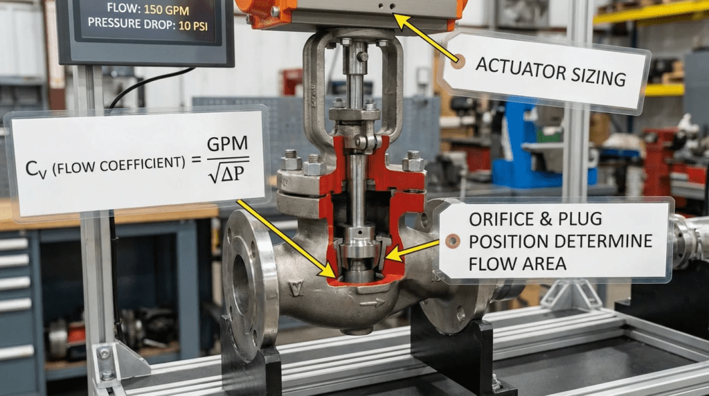
The flow coefficient (Cv) is defined as the number of US gallons of water per minute at 60°F that will flow through a valve with a pressure drop of 1 psi. Sizing is a sequential process:
- Calculate Required Cv: For incompressible fluids (water, wastewater), the basic simplified equation is:
Cv = Q × √(G / ΔP)
Where Q = Flow rate (GPM), G = Specific gravity (1.0 for water), and ΔP = Pressure drop across the valve (psi). - Account for Piping Geometry: If the valve is smaller than the line size, reducers and expanders will create additional pressure losses. Engineers must apply the Piping Geometry Factor (FP) to adjust the calculated Cv.
- Check for Choked Flow & Cavitation: Calculate the maximum allowable pressure drop (ΔPmax) before the fluid vaporizes at the vena contracta (the narrowest point of flow).
ΔPmax = FL2 × (P1 − rc × Pv)
Where FL = Liquid Pressure Recovery Factor (valve specific), P1 = Upstream pressure (psia), Pv = Vapor pressure of the fluid (psia), and rc = Critical pressure ratio. If actual ΔP exceeds ΔPmax, choked flow and cavitation are occurring. - Select Valve Size: Compare the calculated Cv values against the manufacturer’s published inherent Cv curves. Select a valve size where the normal flow falls roughly between 40% and 60% open, minimum flow is above 10% open, and maximum flow is below 85% open.
As water accelerates through the valve trim, its pressure drops. If the pressure at the vena contracta drops below the fluid’s vapor pressure, vapor bubbles form (flashing). As the fluid exits the valve and velocity decreases, pressure recovers. If pressure recovers above the vapor pressure, the bubbles violently collapse (cavitation), creating microscopic shockwaves that blast metal off the valve internals. Understanding a valve’s FL rating is critical to preventing this.
Specification Checklist
A rigorous specification protects the municipality or industrial client from inferior products. Always include:
- Calculated min/norm/max Cv requirements, not just pipeline diameter.
- Inherent flow characteristic (Linear, Equal Percentage, Quick Open).
- Maximum allowable sound pressure level (typically 85 dBA at 1 meter).
- Required Liquid Pressure Recovery Factor (FL) based on cavitation calculations.
- FCI 70-2 Leakage Class.
- Specific elastomer materials (e.g., peroxide-cured EPDM for chloramines).
- Actuator sizing safety factor (minimum 1.25x to 1.5x maximum dynamic torque/thrust).
Standards & Compliance
Adherence to industry standards ensures safety, interoperability, and durability. Key standards for control valves include:
- ISA-75.01.01: Flow Equations for Sizing Control Valves. The universal mathematical standard.
- FCI 70-2: Control Valve Seat Leakage. Defines the acceptable leakage rates (Classes I through VI) for control valves.
- AWWA C504/C507: While primary AWWA standards apply mostly to isolation butterfly and ball valves, many municipalities require control valves to meet applicable sections (like shaft diameters and coating thicknesses).
- ISA-75.11.01: Inherent Flow Characteristic and Rangeability of Control Valves.
FAQ SECTION
What is Control Valves Sizing and Selection: Cv?
Control Valves Sizing and Selection: Cv refers to the engineering process of calculating a valve’s required flow coefficient (Cv) based on process variables, and selecting the appropriate valve type, size, and trim to provide stable control. Cv represents the volume of water (in GPM) that passes through a valve with a 1 psi pressure drop. Proper sizing prevents premature mechanical failure, severe cavitation, and process control instability.
What is the difference between an inherent and installed flow characteristic?
The inherent characteristic is how the valve’s capacity (Cv) changes with travel under a constant, laboratory-controlled pressure drop. The installed characteristic is how the valve behaves in a real piping system, where the available pressure drop changes as flow changes. Because piping friction consumes more system pressure at high flows, an “Equal Percentage” inherent characteristic usually warps into a “Linear” installed characteristic, which is highly preferred for stable PID tuning.
Why do control valves cavitate, and how can it be prevented?
Cavitation occurs when fluid pressure drops below its vapor pressure at the narrowest point inside the valve (vena contracta), forming bubbles. As pressure recovers downstream, these bubbles violently collapse, destroying metal. Prevention involves selecting valves with a high Liquid Pressure Recovery Factor (FL), using multi-stage anti-cavitation trims that drop pressure in small steps, or increasing downstream backpressure to keep the system pressure above the vapor pressure.
How do you address valve stiction in control loops?
Stiction (static friction) occurs when the friction between the valve stem and the packing box is too high. The PLC sends a signal, but the valve doesn’t move until the actuator builds enough force to overcome the friction, causing the valve to suddenly jump past the setpoint. It is addressed by replacing worn packing, lubricating the stem, ensuring the actuator is properly sized to overpower friction easily, and using high-quality digital positioners that utilize specialized friction-compensation algorithms.
What is the typical lifespan of a control valve in wastewater service?
In municipal wastewater, heavy-duty control valves typically last 15 to 25 years with regular preventative maintenance. However, soft goods (elastomers, diaphragms, packing) generally require replacement every 3 to 5 years. Severe service trims (like those handling abrasive primary sludge or high-pressure RO reject) may require replacement every 2 to 4 years. The Maintainability, Safety & Access section above details how top-entry designs can streamline this replacement process.
Why shouldn’t I specify a control valve to be the same size as the piping?
Control valves must create a pressure drop to regulate flow. If a valve is the same size as the pipeline (line-sized), it will typically possess an inherently oversized Cv. This forces the valve to throttle while nearly closed (e.g., 5-15% open). Operating continuously near the seat causes high-velocity wire-drawing, poor control resolution, and rapid mechanical wear. Properly sized control valves are usually one or two sizes smaller than the connecting pipe.
Do hydraulic circuit valves belong in a control valve specification?
Not in the pipeline specification, but they belong in the project. Any electro-hydraulically actuated valve or gate depends on a hydraulic circuit containing directional control, proportional or servo, counterbalance, and load-holding elements, and the performance of that circuit sets the resolution, holding capability, and failure behaviour of the assembly. A control valve specification that defines deadband and fail position at the valve while leaving the hydraulic circuit to a subcontractor frequently produces an installation that meets neither. Where electro-hydraulic actuation is specified, the circuit elements should be named and their centre conditions and load-holding arrangements defined alongside the valve trim.
CONCLUSION
Key Takeaways
- Never Line-Size: Always calculate the required Cv for minimum, normal, and maximum flow rates. Valves are typically 1 to 2 sizes smaller than the pipe.
- Mind the Cavitation: Calculate the maximum allowable pressure drop (ΔPmax). If your application exceeds it, anti-cavitation trim or systemic redesign is mandatory to prevent rapid destruction.
- Valve Authority Matters: Ensure the valve takes at least 25% to 33% of the total system dynamic pressure drop at design flow to maintain control over the process.
- Match Characteristic to Process: Use Equal Percentage inherent characteristics for most liquid flow and level control loops to achieve an installed Linear response.
- Prioritize O&M: Specify top-entry bodies, smart positioners with diagnostics, and bypass loops to dramatically lower total lifecycle costs and operator burden.
- The Valve Is an Assembly: Body, trim, actuator, and positioner are specified together or they fail together; deadband and fail behaviour are properties of the whole assembly, not of the trim alone.
The successful automation of water and wastewater treatment facilities depends entirely on the mechanical interface between the control system and the fluid. Mastering Control Valves Sizing and Selection: Cv ensures that this interface is reliable, predictable, and robust. Engineers must shift away from the practice of casually matching valve sizes to pipe diameters and instead embrace rigorous hydraulic calculation methodologies. By understanding the dynamic relationship between flow rate, pressure drop, specific gravity, and the valve’s flow coefficient, specifying engineers can eliminate the root causes of hunting, cavitation, and premature mechanical wear.
When approaching new designs or retrofitting problematic installations, plant directors and design engineers must balance CAPEX limitations with lifecycle realities. While highly engineered globe valves with specialized trims require a larger initial investment, their ability to withstand severe pressure drops and abrasive process fluids often yields a lower total cost of ownership compared to replacing standard butterfly valves every few years. Furthermore, integrating smart positioner technology transitions maintenance strategies from reactive firefighting to proactive, data-driven management.
Ultimately, a control valve is the most critical mechanical asset in an automated loop. By applying the formulas, material sciences, and maintenance strategies outlined in this guide, utilities can ensure process stability, protect upstream and downstream equipment, and achieve long-term compliance with environmental treatment standards. The subcategory sections above cover manufacturer selection and flow control fundamentals, and set out where the hydraulic circuit elements fit for anyone specifying electro-hydraulic actuation.